EasyManua.ls Logo

Mooney M20K - Fuselage Repair

Mooney M20K
437 pages
Print Icon
To Next Page IconTo Next Page
To Previous Page IconTo Previous Page
Loading...
MOONEY
AIRCRAFT
CORPORATION
M20K
SERVICE
AND
MAINTENANCE
MANUAL
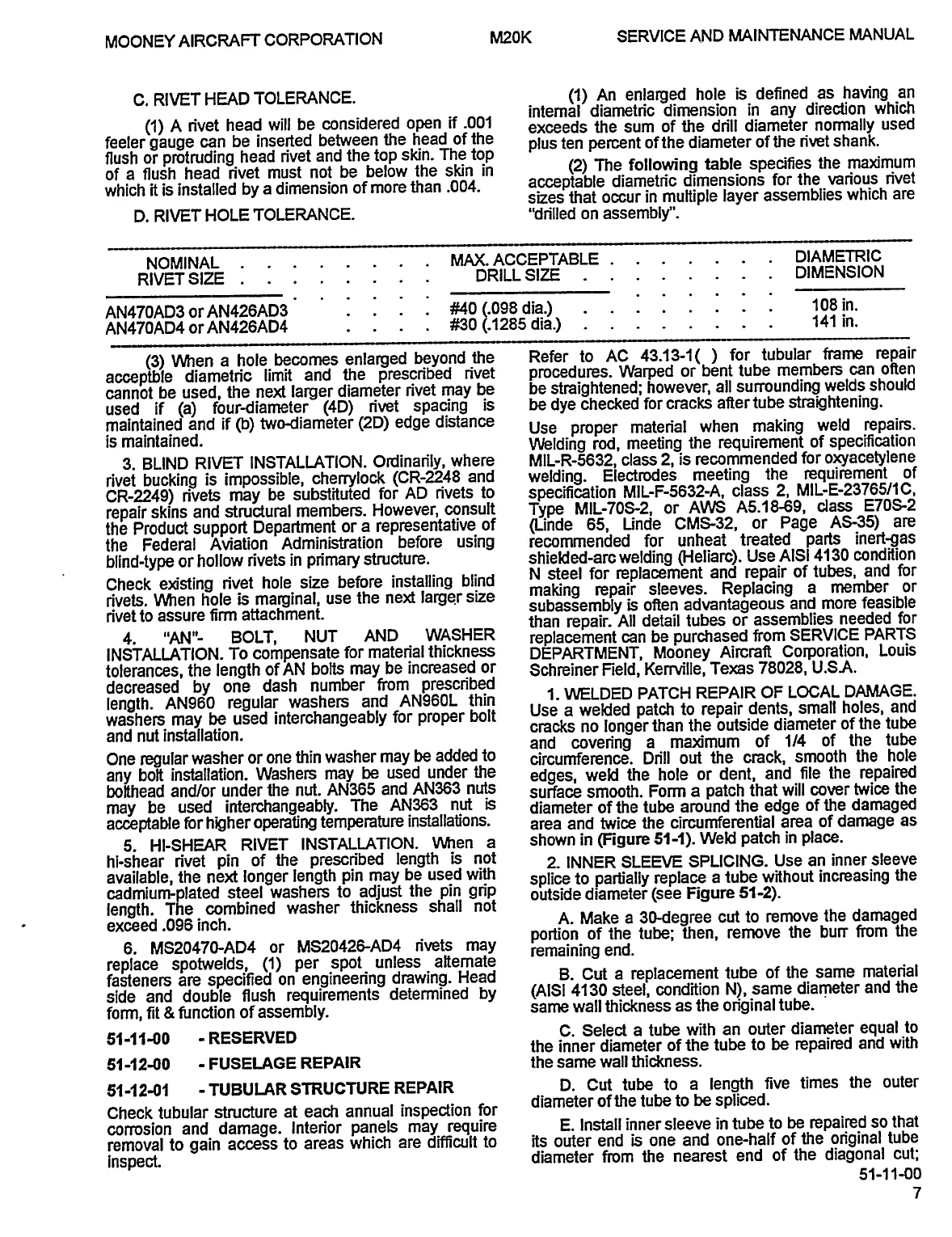
C.
RIVET
HEAD
TOLERANCE.
(1)
An
enlarged
hole
is
defined
as
having
an
internal
diametn’c
dimension
in
any
direction
which
(1)
A
rivet
head
will
be
considered
open
if.001
exceeds
the
sum
of
the
dn’ll
diameter
normally
used
feeler
gauge
can
be
inserted
between
the
head
of
the
plus
ten
percent
of
the
diameter
of
the
rivet
shank.
flush
or
protruding
head
n’vet
and
the
top
skin.
The
top
of
a
flush
head
rivet
must
not
be
below
the
skin
in
(2)
The
following
table
specifies
the
maximum
which
it
is
installed
by
a
dimension
of
more
than
.004.
acceptable
diametric
dimensions
for
the
various
rivet
s~nes
that
occur
in
multiple
layer
assemblies
which
are
D.
RIVET
HOLE
TOLERANCE.
"drilled
on
assembly".
NOMINAL
MAX.
ACCEPTABLE
DIAMETRIC
RIVET
SIZE
DRILL
SIZE
DIMENSION
AN470AD3
or
AN426AD3
#40
(.098
dia.)
108
in.
AN470AD4
or
AN426AD4
#30
(.1285
dia.)
141
in.
(3)
When
a
hole
becomes
enlarged
beyond
the
Refer
to
AC
43.13-1(
for
tubular
frame
repair
acceptble
diametric
limit
and
the
prescn’bed
rivet
procedures.
Warped
or
bent
tube
members
can
often
cannot
be
used,
the
ne>d
larger
diameter
rivet
may
be
be
straightened;
however,
all
surrounding
welds
should
used
if
(9)
four-diameter
(4D)
rivet
spacing
is
be
dye
checked
for
cracks
after
tube
straightening.
maintained
and
if
two-diameter
(2D)
edge
distance
Use
proper
maten‘al
when
making
weld
repairs.
is
maintained.
Welding
rod,
meeting
the
requirement
of
specification
3.
BLIND
RIVET
INSTALLATION.
Ordinan’ly,
where
MIL-R-5632,
class
2,
is
recommended
for
o~acetylene
rivet
bucking
is
impossible,
cherrylock
(CR-2248
and
welding.
Electrodes
meeting
the
requirement
of
CR-2249)
rivets
may
be
substituted
for
AD
rivets
to
specification
MIl-F-5632d,
class
2,
MIL-E-23765/1C,
repair
skins
and
structural
members.
However,
consult
Type
MIL-70S-2,
or
AWS
A5.18-69,
class
E70S-2
the
Product
support
Department
or
a
representative
of
(Linde
65,
Linde
CMS-32,
or
Page
AS-35)
are
the
Federal
Aviation
Administration
before
using
recommended
for
unheat
treated
parts
inert-gas
blind-type
or
hollow
nvets
in
primary
structure.
shielded-are
welding
~-leliarc).
Use
AISI
4130
condition
Check
e>a’sting
rivet
hole
size
before
installing
blind
N
steel
for
replacement
and
repair
of
tubes,
and
for
rivets.
When
hole
is
marginal,
use
the
ne~d
larger
size
making
repair
sleeves.
Replacing
a
member
or
subassembly
is
often
advantageous
and
more
feasible
rivet
to
assure
firm
attachment.
than
repair.
AIl
detail
tubes
or
assemblies
needed
for
4.
"AN’~
BOLT,
NUT
AND
WASHER
replacement
can
be
purchased
from
SERVICE
PARTS
INSTALLATION.
To
compensate
for
material
thickness
DEPARTMENT,
Mooney
Aircraft
Corporation,
Louis
tolerances,
the
length
of
AN
bolts
may
be
increased
or
Schreiner
Field,
Kemn’lle,
Texas
78028,
U.SA.
decreased
by
one
dash
number
from
prescribed
length.
AN960
regular
washers
and
AN960L
thin
1´•
WELDED
PATCH
REPAIR
OF
LOCAL
DAMAGE.
washers
may
be
used
interchangeably
for
proper
bolt
Use
a
welded
patch
to
repair
dents,
small
holes,
and
cracks
no
longer
than
the
outside
diameter
of
the
tube
and
nut
installation.
and
coven’ng
a
maximum
of
1/4
of
the
tube
One
regular
washer
or
one
thin
washer
may
be
added
to
circumference.
Drill
out
the
c~ack,
smooth
the
hole
any
bolt
installation.
Washers
may
be
used
under
the
edges,
weki
the
hole
or
dent,
and
file
the
repaired
bolthead
and/or
under
the
nut.
AN365
and
AN363
nuts
surface
smooth.
Form
a
patch
that
will
cover
twice
the
may
be
used
interchangeably.
The
AN363
nut
is
diameter
of
the
tube
around
the
edge
of
the
damaged
acceptable
for
higher
operating
temperature
installations.
area
and
twice
the
circumferential
area
of
damage
as
5.
HI-SMEAR
RIVET
INSTALLATION.
When
a
shown
in
(figure
51-1).
Weld
patch
in
place.
hi-shear
rivet
pin
of
the
prescribed
length
not
2
INNER
SLEEVE
SPLICING.
Use
an
inner
sleeve
available,
the
next
longer
length
pin
may
be
used
with
splice
to
partially
replace
a
tube
without
increasing
the
cadmium-plated
steel
washers
to
adjust
the
pin
gn’p
outside
diameter
(see
Figure
51-2).
length.
The
combined
washer
thickness
shall
not
exceed.096
inch.
A.
Make
a
~(kiegree
cut
to
remove
the
damaged
portion
of
the
tube;
then,
remove
the
bum
from
the
6.
MS20470-AD4
or
MS20426-AD4
n’vets
may
remaining
end.
replace
spotwelds,
(1)
per
spot
unless
a8emate
fasteners
are
specified
on
engineering
drawing.
Head
B.
Cut
a
replacement
tube
of
the
same
material
side
and
double
flush
requirements
determined
by
(AISI
4130
steel,
condition
N),
same
diameter
and
the
form,
fit
function
of
assembly.
same
wail
thickness
as
the
original
tube.
C.
Select
a
tube
with
an
outer
diameter
equal
to
5111-00
-RESERVED
the
inner
diameter
of
the
tube
to
be
repaired
and
with
51-1290
FUSELAGE
REPAIR
the
same
wall
thickness.
5112-01
TUBULAR
STRUCTURE
REPAIR
D.
Cut
tube
to
a
length
five
times
the
outer
diameter
of
the
tube
to
be
spliced.
Check
tubular
structure
at
each
annual
inspection
for
corrosion
and
damage.
Interior
panels
may
require
E.
install
inner
sleeve
in
tube
to
be
repaired
so
that
removal
to
gain
access
to
areas
which
are
difficult
to
its
outer
end
is
one
and
one-half
of
the
original
tube
inspect,
diameter
from
the
nearest
end
of
the
diagonal
cut;
51-11-00
OLDWILLWAYNE

Table of Contents