EasyManua.ls Logo

Mooney M20K - Horizontal Stabilizer & Vertical Fin Repair

Mooney M20K
437 pages
Print Icon
To Next Page IconTo Next Page
To Previous Page IconTo Previous Page
Loading...
MOONEY
AIRCRAFT
CORPORATION
M20K
SERVICE
AND
MAINTENANCE
MANUAL
1~"
ooooooo
ioooooool~
617,
O
O
O
oooooIooooo
o
o
o
Ir´•-
000000
f000000
oo
o
o
q
o
o
o
o
SWN5l-5
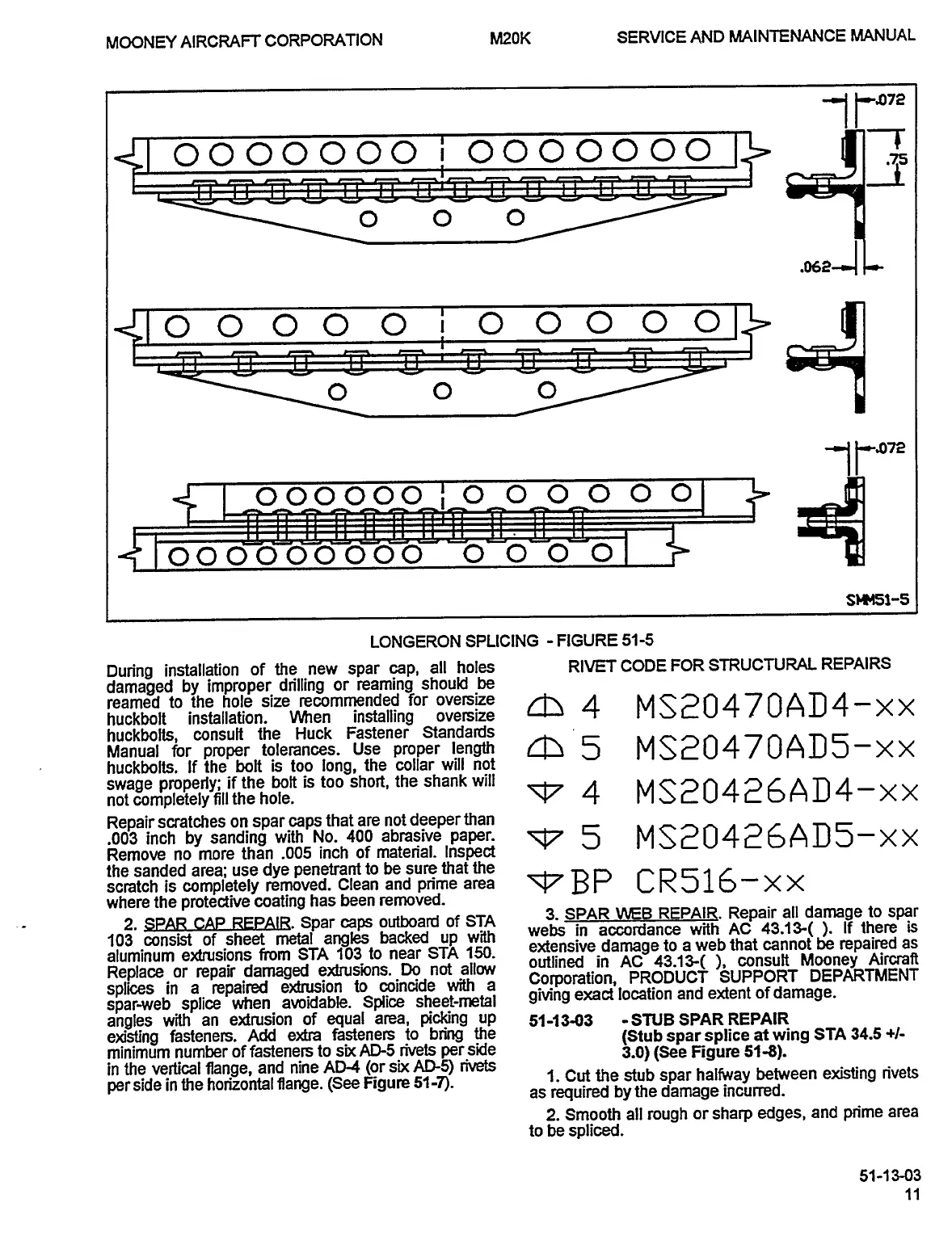
LONGERON
SPLICING
FIGURE
51-5
During
installation
of
the
new
spar
cap,
all
holes
RIVET
CODE
FOR
STRUCTURAL
REPAIRS
damaged
by
improper
drilling
or
reaming
should
be
reamed
to
the
hole
size
recommended
for
oversize
dzs
4
MSE~0470AD4-xx
huckbolt
installation.
When
installing
oversize
huckbolts,
consult
the
Huck
Fastener
Standards
Manual
for
proper
tolerances.
Use
proper
length
4~
5
MS~0470AD5-xx
huckbolts.
If
the
bolt
is
too
long,
the
collar
will
not
swage
properly;
if
the
bolt
is
too
short,
the
shank
will
~7
4
MS~0426AD4-xx
not
completely
fill
the
hole.
Repair
scratches
on
spar
caps
that
are
not
deeper
than
.003
inch
by
sanding
with
No.
400
abrasive
paper.
~5
MS~0426AD5-xx
Remove
no
more
than
.005
inch
of
material.
Inspect
the
sanded
area;
use
dye
penetrant
to
be
sure
that
the
~BP
CR516-xx
scratch
is
completely
where
the
protective
coating
has
been
removed.
2.
SPAR
CAP
REPAIR.
Spar
caps
outboard
of
STA
3.
SPAR
WEB
REPAIR.
Repair
all
damage
to
spar
webs
in
accordance
with
AC
43.13-(
If
there
is
103
consist
of
sheet
metal
angles
backed
up
with
aluminum
e~dtusions
from
STA
103
to
near
STA
150.
e~densive
damage
to
a
web
that
cannot
be
repaired
as
Replace
or
repair
damaged
e~husions.
Do
not
allow
outlined
in
AC
43.13-(
consult
Mooney
Aircraft
splices
in
a
repaired
e>drusion
to
coincide
with
a
Corporation,
PRODUCTSUPPORT
DEPARTMENT
spar-web
splice
when
avoidable.
Splice
sheet-metal
giving
exact
location
and
extent
of
damage.
angles
with
an
e>drusion
of
equal
area,
picking
up
51-13-03
-SNB
SPAR
REPAIR
existing
fasteners.
Add
e~dra
fasteners
to
bring
the
(Stub
spar
splice
at
wing
STA
34.5
+1-
minimum
number
of
fasteners
to
six
AD5
rivets
per
side
3.0)
(See
Figure
51-8).
in
the
vertical
flange,
and
nine
AD-4
(or
s’oc
AD-5)
rivets
per
side
in
the
horizontal
flange.
(See
Figure
51-7).
1.
Cut
the
stub
spar
halfway
between
existing
rivets
as
required
by
the
damage
incurred.
2.
Smooth
all
rough
or
sharp
edges,
and
prime
area
to
be
spliced.
51-1
3-03
OLDWILLWAYNE

Table of Contents