EasyManua.ls Logo

Mooney M20K - Trouble Shooting SDI (Hoskins) Fuel Management Systems

Mooney M20K
437 pages
Print Icon
To Next Page IconTo Next Page
To Previous Page IconTo Previous Page
Loading...
MOONEY
AIRCRAFT
CORPORATION
M20K
SERV(CE
AND
MAINTENANCE
MANUAL
K1
K3
K5
K7
ol
IK)
-0101
IK)
OJ
OI
IK)
~010
K-FACT17R(lro
c~
0
I
lo
K,
-oll
Irol
o
I
lo
A
o
ooo
ooo
ooo
ooolK-F~ACT[7R
NI3T
USED
o
o
o
o
o
o
o
o
o
o
o
o
000
000
000
000
000
000
000
000
UNITS
000
000
000
000
M
L
K
M
L
K
M
L
K
M
L
K
US,
GALLONS
IMP.
GAUJ3NS
POUNI)S
UTERS
oool
To
ool
lo
oO_l
looo
K-FACTI7R(lo
ool
loool
ioool
looo
B
o
0
ooo
ooo
000
oool
UNITS
NOT
USED(lo
0
ol
lo
0
ol
lo
0
ol
lo
o
o
000
000
000
000
O
OK>-C~
O
O
UNITS
or
ILO
01
0
0
lo
at
to
to
at
rSM73-31
MLK
MLK
MLK
MLK
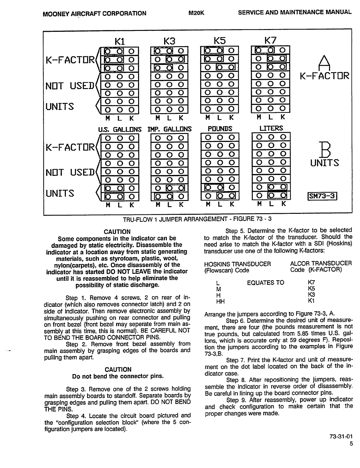
TRU-FLOW
1
JUMPER
ARRANGEMENT
FIGURE
73
3
CAUTION
Step
5.
Determine
the
K-factor
to
be
selected
Some
components
in
the
indicator
can
be
to
match
the
K-factor
of
the
transducer.
Should
the
damaged
by
static
electricity.
Disassemble
the
need
arise
to
match
the
K-factor
with
a
SDI
(Hoskins)
indicator
at
a
location
away
from
static
generating
transducer
use
one
of
the
following
K-factors:
materials,
such
as
styrofoam,
plastic,
wool,
nylon(carpets),
etc,
Once
disassembly
of
the
HOSKINS
TRANSDUCER
ALCOR
TRANSDUCER
indicator
has
started
DO
NOT
LEAVE
the
indicator
(Flowscan)
Code
Code
(K-FACTOR)
until
it
is
reassembled
to
help
eliminate
the
possibility
of
static
discharge.
L
EQUATES
TO
K7
M
K5
Step
1.
Remove
4
screws,
2
on
rear
of
in-
H
K3
HH
K1
dicator
(which
also
removes
connector
latch)
and
2
on
side
of
indicator.
Then
remove
electronic
assembly
by
Arrange
the
jumpers
according
to
Figure
73-3,
A.
simultaneously
pushing
on
rear
connector
and
pulling
Step
6.
Determine
the
desired
unit
of
measure-
on
front
bezel
(front
bezel
may
seperate
from
main
as-
ment,
there
are
four
(the
pounds
measurement
is
not
sembly
at
this
time,
this
is
normal).
BE
CAREFUL
NOT
true
pounds,
but
calculated
from
5.85
times
U.S.
gal-
TO
BEND
THE
BOARD
CONNECTOR
PINS.
ions,
which
is
accurate
only
at
59
degrees
Fl.
Reposi-
Step
2.
Remove
front
bezel
assembly
from
tion
the
jumpers
according
to
the
examples
in
Figure
main
assembly
by
grasping
edges
of
the
boards
and
73-3,B.
pulling
them
apart.
Step
7.
Print
the
K-factor
and
unit
of
measure-
ment
on
the
dot
label
located
on
the
back
of
the
in-
CAUTION
Do
not
bend
the
connector
pins.
dicator
case.
Step
8.
After
repositioning
the
jumpers,
reas-
Step
3.
Remove
one
of
the
2
screws
holding
semble
the
indicator
in
reverse
order
of
disassembly.
main
assembly
boards
to
standoff.
Separate
boards
by
Be
careful
in
lining
up
the
board
connector
pins.
grasping
edges
and
pulling
them
apart.
DO
NOT
BEND
Step
9.
After
reassembly,
power
up
indicator
THE
PINS.
and
dheck
configuration
to
make
certain
that
the
Step
4.
Locate
the
circuit
board
pictured
and
P’oper
changes
were
made.
the
"configuration
selection
block"
(where
the
5
con-
figuration
jumpers
are
located).
73-31-01
OLDWILLWAYNE

Table of Contents