EasyManua.ls Logo

Mooney M20K - General; Oil Filter Removal; Oil Filter Installation; Distribution

Mooney M20K
437 pages
Print Icon
To Next Page IconTo Next Page
To Previous Page IconTo Previous Page
Loading...
MOONEY
AIRCRAFT
CORPORATION
M20K
SERVICE
AND
MAINTENANCE
MANUAL
79-0090
-GENERAL
The
engine
oil
filter,
TCM
P/N
641583,
should
be
The
oil
system
is
a
wet
sump,
pressure
type
system.
replaced
each
50
hours
and
at
every
oil
change
(refer
The
engine
sump
has
an
8
quart
(U.S~
capacsty.
to
Figu~
742
for
location).
Servicing
of
the
oil
quantity
is
provided
through
an
1.
Remove
top
and
bottom
cowling
(see
Sedion
access
door
located
on
top
of
the
engine
cowling.
71-10-00).
The
airaaff
is
delivered
with
the
proper
non-detergent,
2.
Cut
and
remove
safety
wire
on
filter
mineral
oil
(MIL-C-6529
Type
II).
This
oil
should
be
changed
at
25
hours
or
when
oil
consumption
has
3.
Loosen
the
spin
off
oil
filter
and
remove.
stabilized.
The
replacement
oil
should
conform
to
TCM
79-00-02
OIL
FILTER
INSTALLATION
Specification
MHS-24(
The
routine
oil
change
interval
is
100
hours,
however
a
operating
in
a
dusty
1´•
Position
new
filter
on
adapter.
environment
the
interval
should
be
more
often.
2.
Tighten
per
instructions
on
filter.
NOTE
3.
Safety
wire
filter.
A
new
remanufactured
or
newly
overhauled
4.
Perform
leak
check
prior
to
flight.
engine
~hould
have
the
oil
and
filter
changed
at
50
hours
of
operation
after
changing
to
5.
Reinstall
lower
and
upper
cowling
(see
Sedion
detergent
oil,
then
begin
the
100
hour
oil
71-11-00).
change
interval.
6.
Conned
and
secure
all
electrical
and
mechanical
connedions.
NOTE
Refer
to
Section
5-20-07
or
to
TCM
TS10360-GB
79-20-00
DISTRIBUTION
Operator’s
Manual
Form
No.
X30536,
Section
VIII,
Form
No.
X30571
for
the
-LB
engine
or
The
oil
system
on
the
TSIO-360-GB,-LB,
-MB
3
-SB
Form
No.
X30584,
Section
VIII,
for
the
-MB
engine
is
internal
within
the
engine
except
for
SE
engine
for
approved
oil
products,
turbocharger
lubrication
and
oil
pressure
transducer
plumbing.
This
portion
of
the
system
contains
pressure
hoses,
fittings
and
check
valves
to
route
oil
through
the
turbocharger
back
to
the
engine
case
for
cooling;
(refer
to
Figure
79-2,
793
and
79-4
for
25-0001
thru
25-0999
7990-01
OIL
FILTER
REMOVAL
and
Figure
79-5,
79-6
for
25-1000
thru
25-TEA).
CIYYUTI
~lll*G
CRINIYUII
~IIIING
nla~la
OVY(IYO
,oL(a
s*~rl
wctssorcr
DRIVL
hlVru;r
NNI
OLUWMRI~E+YRI
gl~
rlYrl~rUR(
COIIIIOC
VUYL
f
I
~3L
1
at
coaro
OPlOlr
´•S´•~UP
O(L
T~YLRINR(
C(LUI~M
VUVL
IUI~OC)uRGIO
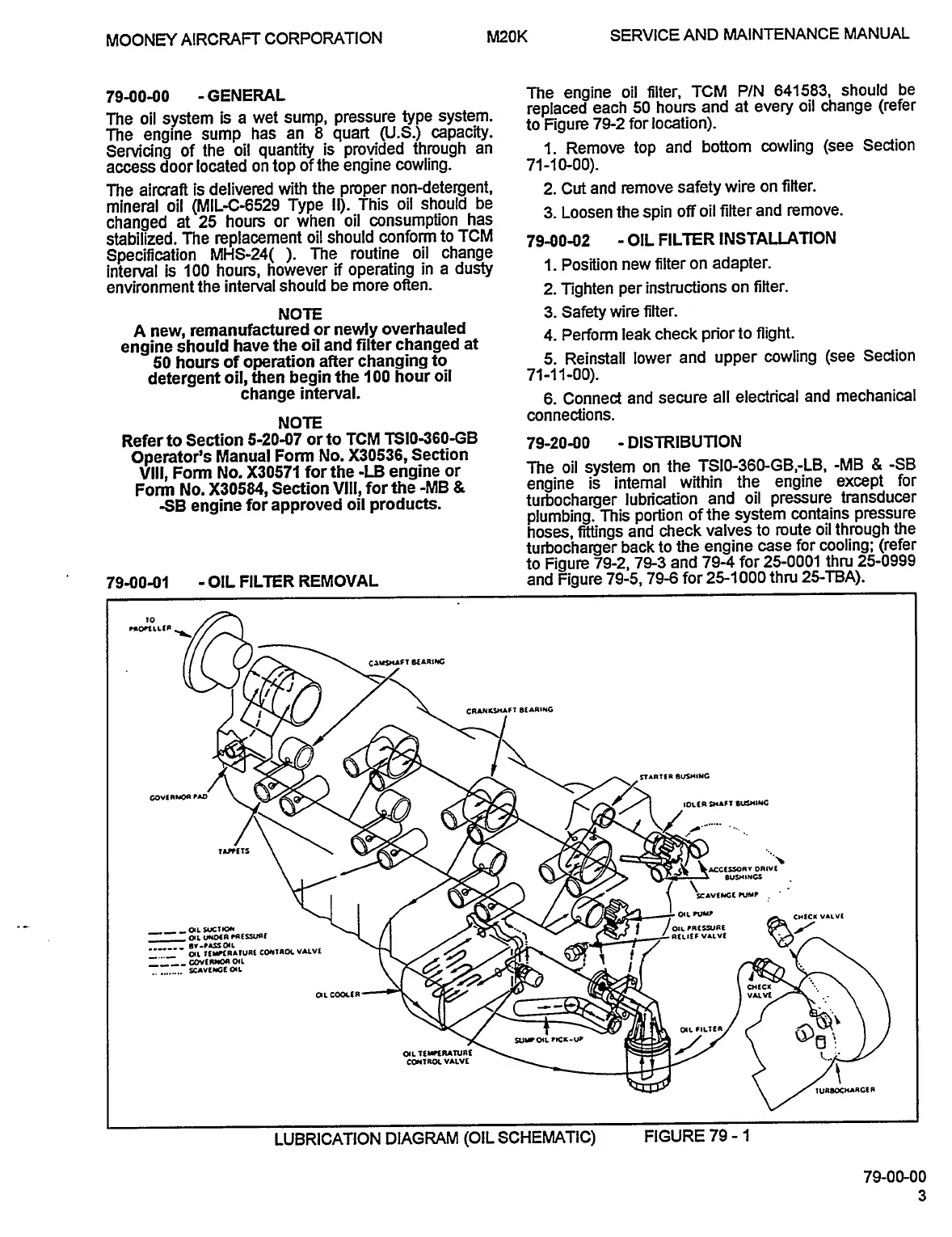
LUBRICATION
DIAGRAM
(OIL
SCHEMATIC)
FIGURE
79
1
79-00-00
OLDWILLWAYNE

Table of Contents