11
Rev. 1.0
11/08/2017
STF-EC Hardware Manual
400-820-9661
2.6 Connecting the motor
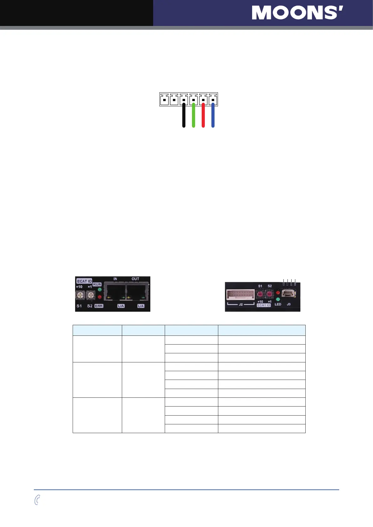
For MOONS’ stepper motor, Connect the motor cable’s black, green, red and blue wires
respectively to the drive’s A+, A-, B+ and B-connections.
J1
Motor Connector
If using a non-MOONS’ motor, please refer to your motor specs for wiring information.
2.7 Connecting the EtherCAT
Dual RJ-45 connectors accept standard Ethernet cables and are categorized as 100BASE-TX
(100 Mb/sec) ports. CAT5 or CAT5e (or higher) cables should be used. The IN port connects to a
master, or to the OUT port of an upstream node. The OUT port connects to a downstream node.
If the drive is the last node on a network, only the IN port is used. No terminator is required on the
OUT port.
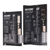
2.7.1 EtherCAT Status Indicator LEDs
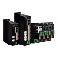
The LEDs are used for indicating status of the EtherCAT. STF05/10-EC have two Link/Activity
LEDs (one for each RJ-45 Ethernet connector) and two status LEDs (RUN and ERR). STF03/06-
EC’s four EtherCAT indicator LEDs are above the connector J3.
L/A OUT
L/A IN
ERR
RUN
STF05/10-EC STF03/06-EC
LED Color Status Description
Link/Activity Green
OFF no Ethernet connection
ON Ethernet is connected
Flickering activity on line
RUN Green
OFF initialization state
Blinking pre-operational state
Single Flash safe-operational state
ON operational state
ERR Red
OFF no error
Blinking general error
Single Flash sync error
Double Flash watch dog error
Notes:
• Flickering: Rapid ashing with a period of approximately 50ms (10Hz)
• Blinking: Flashing with equal on and off periods of 200ms (2.5Hz)
• Single Flash: Repeating on for 200ms and off for 1s
• Double Flash: Two ashes with a period of 200ms followed by off for 1s