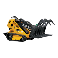
Operating Controls
2.7
Operating Controls Description (Continued)
DO NOT attach an auxiliary hydraulic cylinder to the Operator Presence control.
Hydraulic pressure will not be held in the system when the Operator Presence control is
returned to the NEUTRAL position.
7.
Track Widen Control – Pushing the lever forward widens the track. Pulling the
lever backwards retracts the track to the normal track width.
NOTE: Do not activate this control unless the machine is traveling either slowly forward or
slowly backward.
8.
Attachment Hydraulic Cylinder Activation Lever – Moving this lever into the
FORWARD detent position extends the hydraulically powered attachment’s
hydraulic cylinder. Moving the control lever into the BACKWARD detent position
retracts the hydraulically powered attachment’s hydraulic cylinder.
9.
Right Hand Grip
10. Right Travel Motor Control – Pushing the lever forward rotates the right side
wheels for forward travel. Pulling the lever backwards rotates the right side wheels
for reverse travel.
11.
Left Travel Motor Control – Pushing the lever forward rotates the left side wheels
for forward travel. Pulling the lever backwards rotates the left side wheels for
reverse travel.
12.
Left Hand Grip
13. Boom Raise and Lower – This lever controls the raising and lowering of the
boom assembly.
14.
Attachment Tilt – Pushing the lever forwards tilts the attachment plate forwards,
lowering the attachment. Pulling the lever backwards tilts the attachment plate
backwards, raising the attachment.
15.
Travel Crawl Speed Control – When a hydraulically powered auxiliary
attachment is in use, this control allows the operator to adjust the machine travel
speed.
16. Engine Throttle - Moving the control lever upwards increases the engine speed
and moving the lever downwards slows the engine speed.
17. Access Panel Lock Levers
18. Lower Service Access Panel – This panel enables access to the engine and
hydraulic controls for service procedures.
NOTE: The track tension adjustment tool is located on the back of this panel.
 Loading...