22
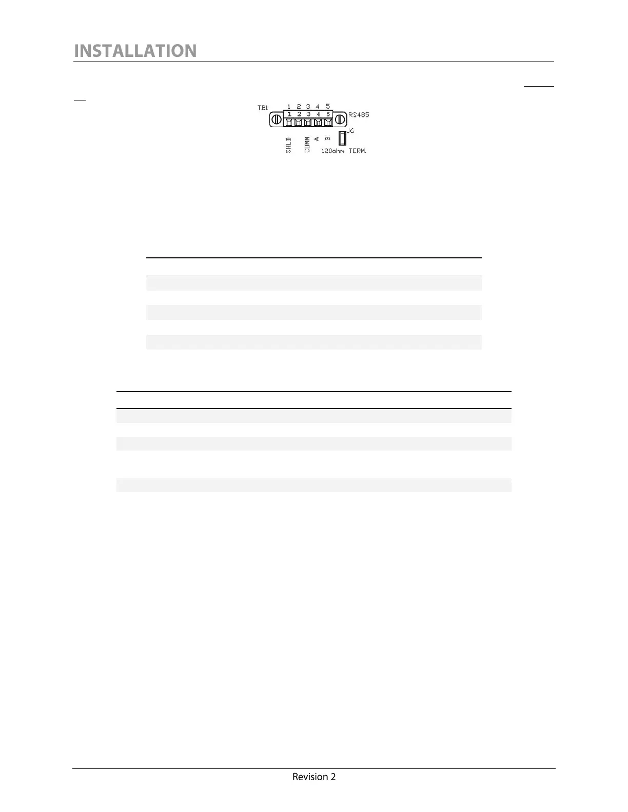
The RS-485 screw-terminal plug-in connector is located on the monitor interface board (See Figure
10).
Figure 10: Calisto/Calisto 2 - RS-485 Connection
It is recommended to un-plug the connector to simplify wiring the connections, and to screw the
connector in place after the connections are made.
The RS-485 connector pinout has the following configuration:
The RS-485 connections must be made in accordance with the following connector ratings:
0.34 – 1.5 mm
2
solid/stranded
Connection range (UL/CSA)
150V (300V preferred
4
),
90ºC (194ºF) or better
The RS-485 common signal ground (pin 3, marked “COMM”) should always be wired properly to
ensure a reliable connection. The signal ground of an RS-485 cable must not be connected to the
chassis ground or “SHLD” when optical or galvanic isolation is used at both ends. Since
Calisto/Calisto 2 provides 1500 V isolation, it is recommended to use RS-485 devices that also offer
good isolation. The signal ground conductor should be connected to pin 3 (COMM) and should be
connected at all ends.
To preserve 1500V functional I/O isolation, 300V rated voltage is preferred.
 Loading...