24
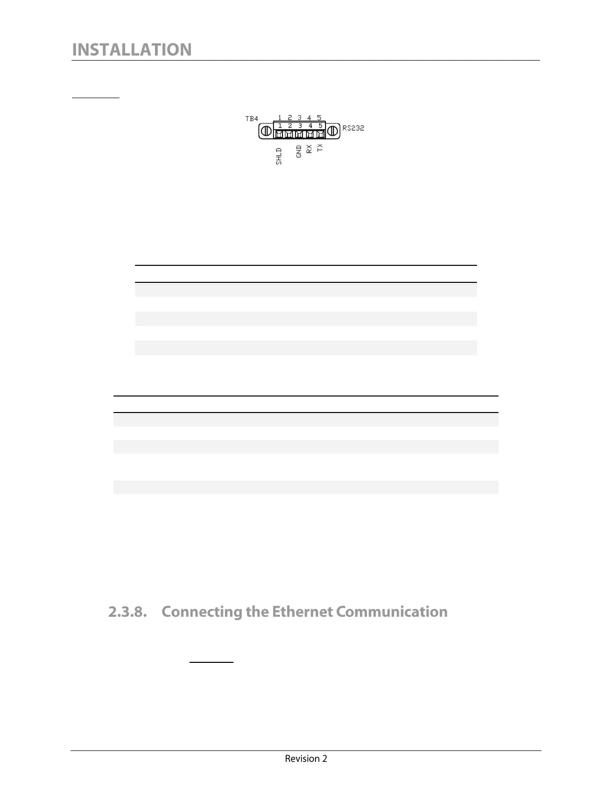
The RS-232 screw-terminal plug-in connector is located on the monitor interface board (see
Figure 11).
Figure 11: Calisto/Calisto 2 - RS-232 Connection
It is highly recommended to select an industrial grade shielded twisted pair cable of minimum 0.34
mm
2
(22 AWG) to set up a communication via RS-232.
The RS-232 connector pinout has the following configuration:
The RS-232 connections must be made in accordance with the following connector ratings:
0.34 – 1.5 mm
2
solid/stranded
Connection range (UL/CSA)
150V (300V preferred
5
),
90ºC (194ºF) or better
The RS-232 signal ground (pin 3, marked “GND”) should always be wired properly to ensure a
reliable connection.
The Calisto/Calisto 2 RS-232 communication port does not support any protocol other than our
proprietary MSSP.
Calisto/Calisto 2 features one Ethernet port which allows the unit to be connected to a computer or
a corporate LAN or WAN. The port is isolated to 1500 V. The port connector is located on the
monitor interface board. Figure 12 illustrates the onboard RJ45 receptacle that can be shielded using
jumper J7 (Ethernet shield to earth ground).
To preserve 1500V functional I/O isolation, 300V rated voltage is preferred.