8
9
DK ENG
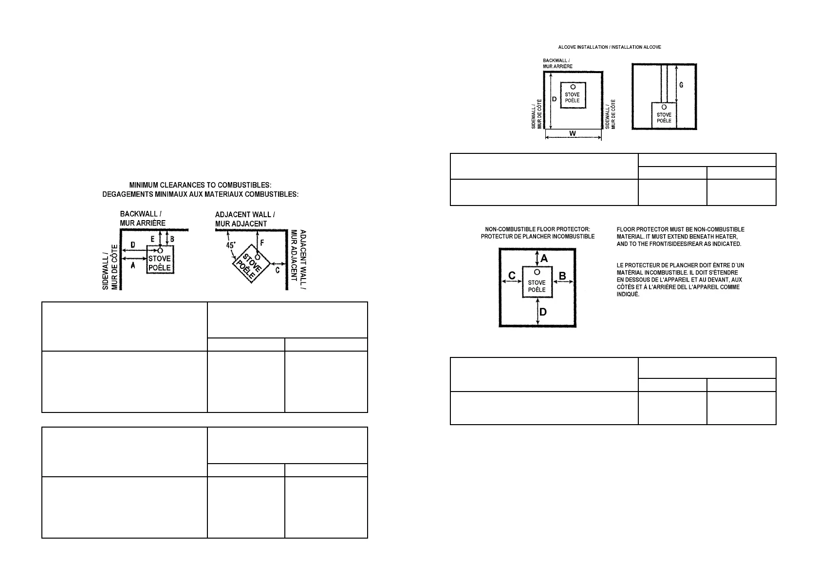
1.5 Positioning the stove
Distance to walls and lintel
When the stove is positioned near combustible materials, observe all current local and na-
tional building regulations with regards to clearances. Distances may need to be increased if
the materials are sensitive to heat. Note also that wall paper and other decorative materials
may become detached with the eects of heat and care should be taken to ensure that they
do not fall towards the stove in such an event.
When the stove is positioned near non-combustible materials, a gap of 4 inches or more is
recommended for cleaning purposes and to ensure that heat circulates around the stove
and out into the room.
In the US, oor protection must be constructed of a non-combustible material and installed
to extend beneath the heater and 16’’ to the front and 8’’ to the sides of the fuel loading
door and ash removal openings. In Canada, oor protection must be constructed of a non-
combustible material and installed to extend beneath the heater and 450 mm.(16’’) to any
side with a door and 200 mm.(8’’) beyond the appliance on the other sides.
CLEARANCE REQUIREMENTS ALCOVE INSTALLATION
USA CANADA
W. Minimum alcove width
D. Maximum alcove depth
G. Alcove ceiling above stove top
32”
24”
36”
815 mm
610 mm
915 mm
FLOOR PROTECTION REQUIREMENTS NONCOMBUSTIBLE MATERIALS
BENEATH STOVE
USA CANADA
A. Extending distance, back
B. Extending distance, right side
C. Extending distance, left side
D. Extending distance, front
-
6”
6”
16”
200 mm
200 mm
200 mm
450 mm
CLEARANCE REQUIREMENTS STANDARD RESIDENTIAL INSTALLATION
INTEGRAL REAR AND BOTTOM SHIELDS
TOP OR REAR VENT
SINGLEWALL CONNECTOR
USA CANADA
A. Sidewall to unit
B. Backwall to unit
C. Cornerwall to unit
D. Sidewall to connector
E. Backwall to connector
F. Cornerwall to connector
G. Unit to ceiling
H. Floor to ceiling
8”
10”
7”
13.5”
12”
13”
-
-
205 mm
255 mm
180 mm
345 mm
305 mm
330 mm
-
-
CLEARANCE REQUIREMENTS STANDARD RESIDENTIAL INSTALLATION
INTEGRAL REAR AND BOTTOM SHIELDS
TOP OR REAR VENT
DOUBLEWALL CONNECTOR
USA CANADA
A. Sidewall to unit
B. Backwall to unit
C. Cornerwall to unit
D. Sidewall to connector
E. Backwall to connector
F. Cornerwall to connector
G. Unit to ceiling
H. Floor to ceiling
8”
6”
7”
-
-
-
-
-
205 mm
150 mm
180 mm
-
-
-
-
-