1
2
3
4
5
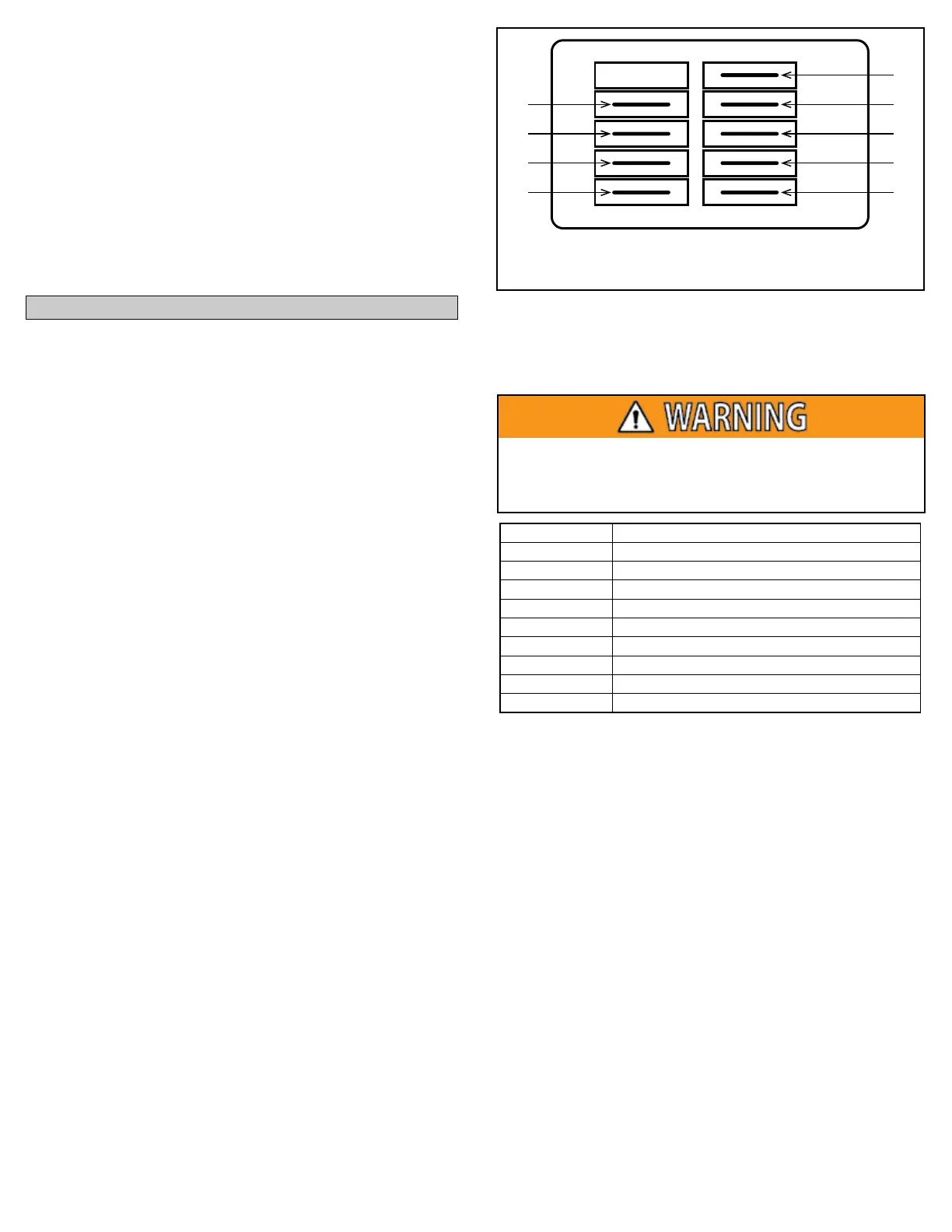
C
L
G
N
Terminal Connection
C Speed Tap Common - 24 VAC Common
L Supply Voltage - 240 Vac Line 1
G Ground Connection
N Supply Voltage - 240 Vac Line 2
1 Low Speed Tap - 24 VAC Input
2 Medium-Low Speed Tap - 24 VAC Input
3 Medium Speed Tap - 24 VAC Input
4 Medium-High Speed Tap - 24 VAC Input
5 High Speed Tap - 24 VAC Input
MORTEX PRODUCTS INC. 501 TERMINAL RD FORT WORTH, TX 76106 Page 10
SECTION 5: TROUBLESHOOTING
The following checks should be made before troubleshooting
the furnace controls for a no-heat issue.
1. Check all of the circuit breakers in the main electrical panel and
on the furnace control box cover to make sure they are in the
“ON” position and have not tripped.
2. Check the 3-amp low voltage fuse on the left side of the control
box. If the fuse is blown, check the wiring with an ohmmeter for
a short to ground. If shorted, repair the short and replace the fuse.
3. Check any electrical switches that are external to the furnace to
make sure they are turned on.
4. Check all wiring connections make sure they are securely fastened.
If the furnace still will not operate, check the following.
1. Check to see if the voltage is above 200 volts for a 208 VAC
power supply and above 220 volts for a 240 VAC power supply.
If there is no voltage or the voltage is low, check the circuit
breakers in the main electrical panel or the electrical supply
wiring to the furnace.
2. If the blower is operating, but there is no heat, check the heater
contactors to be sure they are closing or check the limit controls
to make sure they are not open.
3. If the motor is not running, check for 208 - 240 VAC on the L1
and L2 contactor terminals. Check for 24 VAC at the motor
speed tap terminals connected between the low voltage
terminal block (LVTB) “G” and “C” terminals for continuous fan
operation, between the LVTB “W” and “C” terminals for heating
operation, or between the LVTB “Y” and “C” terminals for cooling
operation.
4. If 240 VAC is present on the L1 and L2 contactor terminals
and 24 VAC is present on the motor speed tap terminals and the
motor is still not operating, replace the motor.
5. Refer to Figure 9 and Table 1 for the motor terminal connections.
To avoid personal injury or property damage, make certain
that the motor leads cannot contact non-insulated metal
components of the unit.
Table 1: Constant Torque Motor Terminal Connections
Heating Element Not Heating
Check for 208 - 240 VAC between terminals T1 and T2 of the
heater contactor(s). If 208 - 240 VAC is present, check the
resistance across the heating element terminals. If the heating
element resistance is infinity (open circuit) for any heating
element, replace the defective heating element.
The heater design is as follows:
• The 5kW and 6kW models have one 5 kW or 6kW heating
element.
• The 8kW and 10 kW models have a heater assembly with two
4kW or 5 kW heating elements.
• The 12kW model has a heater assembly with two 6kW heating
elements.
• The 15 kW model has one heater assembly with two 5 kW
heating elements and one heater assembly with one 5 kW
heating element.
• The 20 kW model has two heater assemblies, each with two 5 kW
heating elements.
Cooling Cycle
When the thermostat is set in the “COOL” mode and the fan
switch on the thermostat is set in the “AUTO” position, a call for
heat completes the circuit between the “R” and “Y” terminals in
the thermostat and 24 VAC is sent from the “Y” thermostat
terminal through the YELLOW thermostat wire to the “Y” terminal
on the low voltage terminal block (LVTB). The blower motor
cooling speed lead is connected to the “Y” terminal on the LVTB
so the blower is energized on the selected cooling speed tap.
The blower will continue to operate until the call for cooling has
been satisfied. The 24 VAC signal is removed from the blower motor
cooling speed tap which de-energizes the blower motor. The
furnace is now in standby mode awaiting the next cooling cycle.
Figure 9: Constant Torque Motor Terminals
Blower Motor FLA
1/3 HP Motor – 2.8
1/2 HP Motor – 4.3
3/4 HP Motor – 6.8