MORTEX PRODUCTS INC. 501 TERMINAL RD FORT WORTH, TX 76106 Page 11
Figure 10: Heater Contactor Terminal Designations
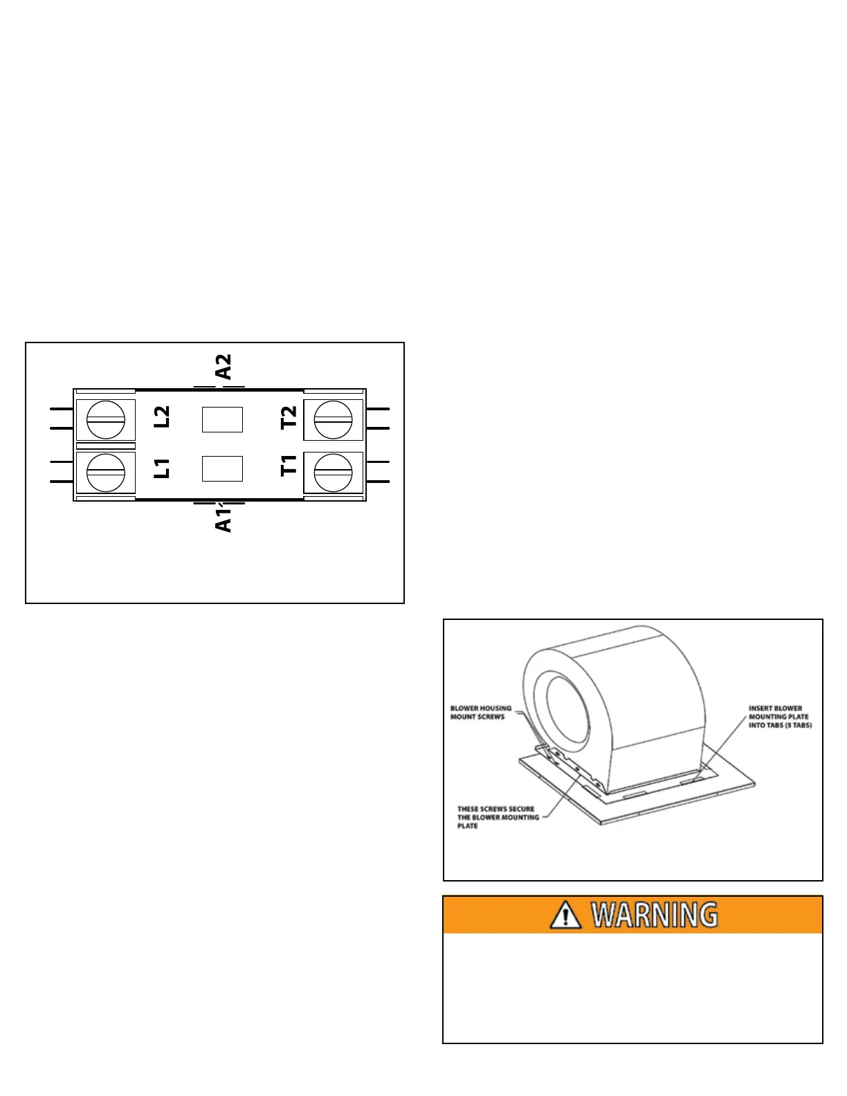
Figure 11: Blower Mounting Plate Screw Locations
Replacing the Blower Motor
1. Follow the instructions as shown in Section 4: Startup and
Shutdown Instructions in the Users Information Manual to
properly shut down this furnace.
2. Remove furnace front access panel and switch the furnace
circuit breaker(s) to the “OFF” position.
3. Disconnect the blower motor 9 pin plastic plug from the top
left corner of the control box (furnace in downow orientation).
4. Remove the two screws on the right side and the screw from
the left side of the blower mounting plate. See Figure 11 for
screw locations.
5. Slide the blower out of the blower compartment and set it on
the oor.
6. Loosen the set screw on the blower wheel hub that secures
the wheel to the blower motor shaft. Make sure the wheel
spins freely with no obstructions. File o any burrs on the
motor shaft before trying to remove the wheel.
7. Remove the 3 screws that secure the motor mounting bracket
legs to the blower housing and remove the motor/bracket
assembly from the blower housing.
8. Disconnect the wires from the motor terminal block after
labeling which terminal each wire was connected to for use
when connecting the wires to the new motor.
9. Remove the blower motor from the motor mounting bracket
by removing the ¼” screw that secure the blower motor to the
bellyband.
10. Insert the new motor and original mounting legs into the
motor mounting bracket and secure to the bellyband and
mounting legs are to the motor with the ¼” screw and nut.
Make sure the belly band and mounting legs are positioned in
the same place as they were on the original motor so the
motor is not at an angle and the wire terminals are located in
the proper position.
11. Insert the 3 screws that secure the motor mounting bracket
legs to the blower housing. Tighten the screws until the
mount bracket arms are securely fastened to the blower housing.
12. Position the blower wheel in the housing until the wheel
is centered between the orices on each side of the housing.
Center the setscrew on the center of the shaft at and tighten
the setscrew securely to hold the wheel in place.
13. Reconnect the wires to the motor terminal block terminals. If
the wires were not labeled in step 8, refer to the wiring
diagram for the correct connections.
14. Plug the motor speed tap connector to the motor terminal.
15. Slide the blower assembly onto the blower deck and attach
the blower assembly to the blower mounting plate with the
screws that were removed in step 4.
16. Connect the 9-pin plastic plug to the 9-pin plastic plug on
the top left corner of the control box (furnace in downow
orientation).
17. Turn the furnace circuit breakers to the “ON” position.
18. Install the furnace front access panel.
19. Follow the instructions in Section 4: Furnace Startup and
Shutdown Instructions found in the Users Information
Manual to properly place the furnace back into service.
20. Turn the thermostat fan switch to the “ON” position and check
for proper blower operation. Make sure the blower does not
make any noises or vibrate during operation.
21. When the blower check is complete, set the thermostat to the
desired mode and temperature.
To avoid personal injury, take precautions to not touch
non-insulated electrical components.
Avoid wearing loose clothing or any items that can become
caught in moving parts, such as the blower wheel. This can
cause serious personal injury.
The correct heating element amp draw is approximately as
follows:
4 kW Heating Element = 16.7 amps
5 kW Heating Element = 20.8 amps
6 kW Heating Element = 25.0 amps
If the heating element current draw is below the amps shown
above or at 0.0, replace the heating element.
If 208 - 240 VAC is not present between the T1 and T2 terminals
(load) of a heater contactor, but there is 208-240 VAC present
between terminals L1 and L2 (line) of that heater contactor,
check for an open limit control and replace the open limit
control if it has failed open.
If 208-240 VAC is not present between the T1 and T2 terminals
(load) of a heater contactor, but 208-240 VAC is present between
the terminals L1 and L2 (line) of the heater contactor(s) and
there is 24 VAC across the coil of that contactor, replace the
heater contactor.