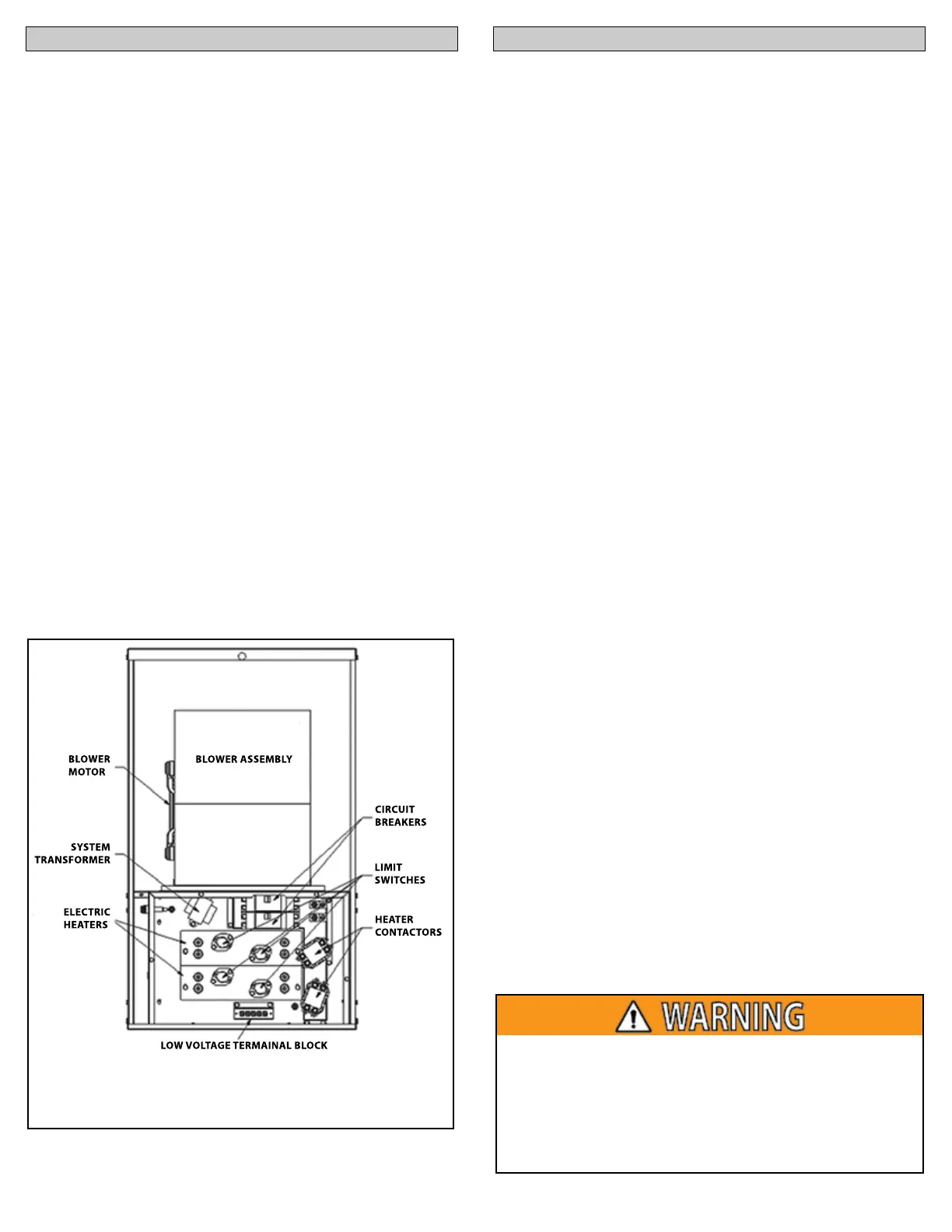
BLOWER
MOTOR
SYSTEM
TRANSFORMER
ELECTRIC
HEATERS
BLOWER ASSEMBLY
CIRCUIT
BREAKERS
LIMIT
SWITCHES
HEATER
CONTACTORS
LOW VOLTAGE TERMAINAL BLOCK
MORTEX PRODUCTS INC. 501 TERMINAL RD FORT WORTH, TX 76106 Page 9
SECTION 3: FURNACE CONTROLS SECTION 4: SEQUENCE OF OPERATION
This section explains how the furnace control operate. Refer to
Figure 8 for component locations.
1. Limit Control(s) – Each electric heating element has a limit
switch directly in front of it to sense the heating element
temperature to prevent overheating. The limit switch opens
if the temperature rises above the set point and interrupts the
24 VAC signal to the heater contactor coil which disconnects
electrical power to the heating element.
2. Heater Contactor(s) –The contactors are controlled by
the thermostat. Upon a call for heat, 24 VAC is sent from the
thermostat “W” terminal to the contactor coil(s) causing the
contactor contacts to close which sends 208/240 VAC to the
electric heating elements. When the call for heat has been
satisfied, the contactor contacts open removing the 208/240
VAC from the heating elements.
3. Circuit Breaker(s) – The circuit breakers are designed as short
circuit protection for the electric heating elements and can also
be used to disconnect the electrical power to the furnace.
NOTE: The circuit breaker(s) are not intended to protect the
wiring from the main control panel (home circuit breaker box)
to the furnace, so the appropriate size breaker(s) or fuse(s) must
be selected (See furnace rating plate) and installed in the main
electrical panel to protect the electrical supply wiring and
furnace.
4. Transformer – The transformer is used to reduce the 208/240
VAC line voltage to 24 VAC which is used by the system control
circuit.
5. 3 Amp Low Voltage Fuse – This fuse is used for over-current
protection of the 24 VAC circuit and transformer.
Figure 8: Component Locations
Continuous Blower
When the thermostat fan switch is in the “ON” position
(continuous indoor fan operation), the circuit between the “R” and
“G” terminals in the thermostat is completed causing 24 VAC to be
sent through the GREEN wire to the “G” terminal on the furnace
low voltage terminal block (LVTB). This energizes the furnace
blower motor and air will be circulated through the ductwork
into the conditioned space. The indoor fan motor will operate
continuously until the thermostat fan switch is switched to the
“AUTO” position.
Intermittent Blower
When the thermostat fan switch is set in the “AUTO” position
(intermittent indoor fan operation), the indoor blower motor
is only energized when there is a call for cooling or heating
operation. Different motor speed taps are typically use for cooling
and heating operating. The indoor fan motor will operate until the
call for cooling or heating is satisfied.
Heating Cycle
When the thermostat is set in the “HEAT” mode and the fan switch
on the thermostat is set in the “AUTO” position, a call for heat
completes the circuit between the “R” and “W” terminals in the
thermostat and 24 VAC is sent from the “W” thermostat terminal
through the WHITE thermostat wire to the W” terminal on the low
voltage terminal block (LVTB).
24 VAC is sent from the LVTB “W” terminal through the limit
controls to the heater contactor coils which closes the contactor
contacts and energizes the heating elements with line voltage.
The blower motor heating speed lead is connected to the “W”
terminal on the LVTB so the blower is energized on the selected
heating speed tap.
The blower will continue to operate until the call for heat has
been satisfied. The electric heater contactor coil is de-energized
which opens the contactor contacts and de-energizes the heating
elements. The 24 VAC signal is also removed from the blower
motor heating speed tap which de-energizes the blower motor.
The furnace is now in standby mode awaiting the next heating
cycle.
The 12 kW, 15 kW and 20 kW models have a BLACK wire that can
be disconnected from the spade terminal on the back of the LVTB
“W” terminal and connected to the wire from the thermostat
“W2” terminal (2nd stage heat) for two-stage heating operation.
A thermostat that has the second stage (W2) heating feature
must be used. The 2nd stage heat cycle is enabled when the room
temperature falls approximately 3 below the thermostat set
point. Once the room temperature is within approximately 1 of
the thermostat set point, the 2nd stage of heat is de-energized
until the thermostat calls for the 2nd stage heat again.
For personal safety be sure to turn the electrical power
For personal safety, turn the electrical power “OFF” to the
furnace at the main electrical panel (circuit breaker box)
before performing service or maintenance on the furnace.
Homeowners/users should never attempt to perform any
servicing or maintenance which requires opening the furnace
control box covers.