MORTEX PRODUCTS INC 501 TERMINAL RD FORT WORTH, TX 76106 Page 11
SECTION 2: FURNACE MAINTENANCE
This furnace must be inspected, cleaned, and adjusted by a
certied dealer or qualied service technician once a year or
before the start of each heating season. The following items must
be inspected, cleaned, serviced, or replaced if there are signs of
deterioration.
1. The roof jack vent terminal.
2. The furnace roof jack combustion air intake passageways.
Should it be necessary to service the vent / combustion air
intake system, this service must be conducted by a qualied
service agency. The operation of the furnace requires the vent
combustion air intake system to be sealed and have adequate
passageways for venting and combustion air to the furnace.
3. The burners, igniter, and ame sensor.
4. The circulating blower wheel and motor. Check for dirt, dust,
or debris in the blower wheel and motor.
5. The supply air duct system for excessive dust, dirt or debris.
6. The louvered return air door for excessive dust, dirt or debris.
7. All electrical wiring for wear or damage.
8. Check the air-conditioning coil for dust, debris or damage.
9. Check the air-conditioning coil drain pan for proper drainage
to prevent water backup into the furnace.
10. The furnace casing and all interior sheet metal panels or
dividers.
Furnace Cleaning Procedure
NOTE: The cleaning procedure listed below must be performed
by a qualied service agency only!
Burner Removal, Cleaning, and Reinstallation
The main burners should be removed and visually inspected
for dirt and debris accumulation during the annual inspection
and maintenance call. Follow the procedure below if cleaning of
burner is required.
1. Follow the instruction in Section 3: Startup and Shutdown
Instructions of the User Information Manual to properly
shut the furnace o.
2. Remove the burner compartment access panel on the front
of the furnace.
3. Turn o the valve in the gas supply line and loosen the
ground union joint. Refer to Figure 5 on page 7 of the User
Information Manual.
4. Remove the gas line from the gas valve. Be sure to use a
wrench on the gas valve hub (wrench boss) located on the
inlet side of the gas valve to keep the gas valve from rotating
when the gas line is being removed.
5. Remove the electrical wires from the terminals on the gas
valve.
6. Unplug the wires from the ame sensor and ignitor.
7. Remove the sixteen (16) screws from the burner mounting
plate and remove the burner assembly. Refer to Figure 8.
8. Lift the burner assembly up, turning slightly to clear the air
baes and slide the burner assembly back to remove it.
9. Remove dirt or debris using a small soft brush and a vacuum
cleaner.
10. Never clean the burners using water. Water will cause the
burner to corrode or rust.
11. Re-insert the burner assembly between the air baes and
slide forward until the burner mounting plate screw holes line
up with the holes in the burner box.
12. Secure the burner assembly to the burner box with the screws
that were removed in step 7.
13. Reconnect the ame sensor and igniter wires that were
disconnected in step 6.
14. Reconnect the electrical wires to the terminals on the gas
valve.
15. Connect the gas supply line. It is recommended that a new
pipe that is properly chamfered, reamed, and free of burrs and
chips be used. If the old pipe is reused, be sure it is clean and
free of rust, scale, burrs, chips, and old pipe joint compound.
16. Apply pipe joint compound that is approved for all gases only
to the male threads of the pipe joints. Do not apply compound
to the rst two threads nearest the end of the pipe.
17. Use a wrench on the gas valve hub (wrench boss) located
on the inlet side of the gas valve to prevent the gas valve from
rotating when the gas line is being tightened. Do not over
tighten the gas pipe which will damage the gas valve. Use
a torque wrench to tighten the inlet gas pipe to a maximum
of 375 in-lbs. If a torque wrench is not available, hand tighten
the pipe and then turn the pipe an additional ½ – ¾ turn or
until connection is snug and not leaking.
18. Connect the union joint and tighten the union.
19. Turn the manual gas valve to the “ON” position. Refer to
Figure 5.
20. Reinstall the burner compartment access panel on the front
of the furnace.
21. Follow the instructions as shown in Section 3: Startup and
Shutdown Instructions of the User Information Manual to
properly start the furnace.
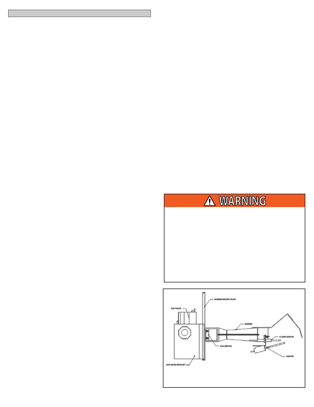
Figure 8: Burner Assembly
Do not over-torque the gas supply pipe into the gas valve.
If the pipe is over tightened, the valve will be damaged.
The furnace manufacturer recommends hand tightening
the gas supply pipe, then tightening an additional ½ - ¾
turn with a wrench or until the connection is snug and not
leaking.
After the gas supply pipe has been tightened, check for
leaks with a commercially available soap solution made
specically for detection of leaks. Never test for gas leaks
with an open ame.
 Loading...
