MORTEX PRODUCTS INC 501 TERMINAL RD FORT WORTH, TX 76106 Page 15
Figure 14: Combustion Air Assembly
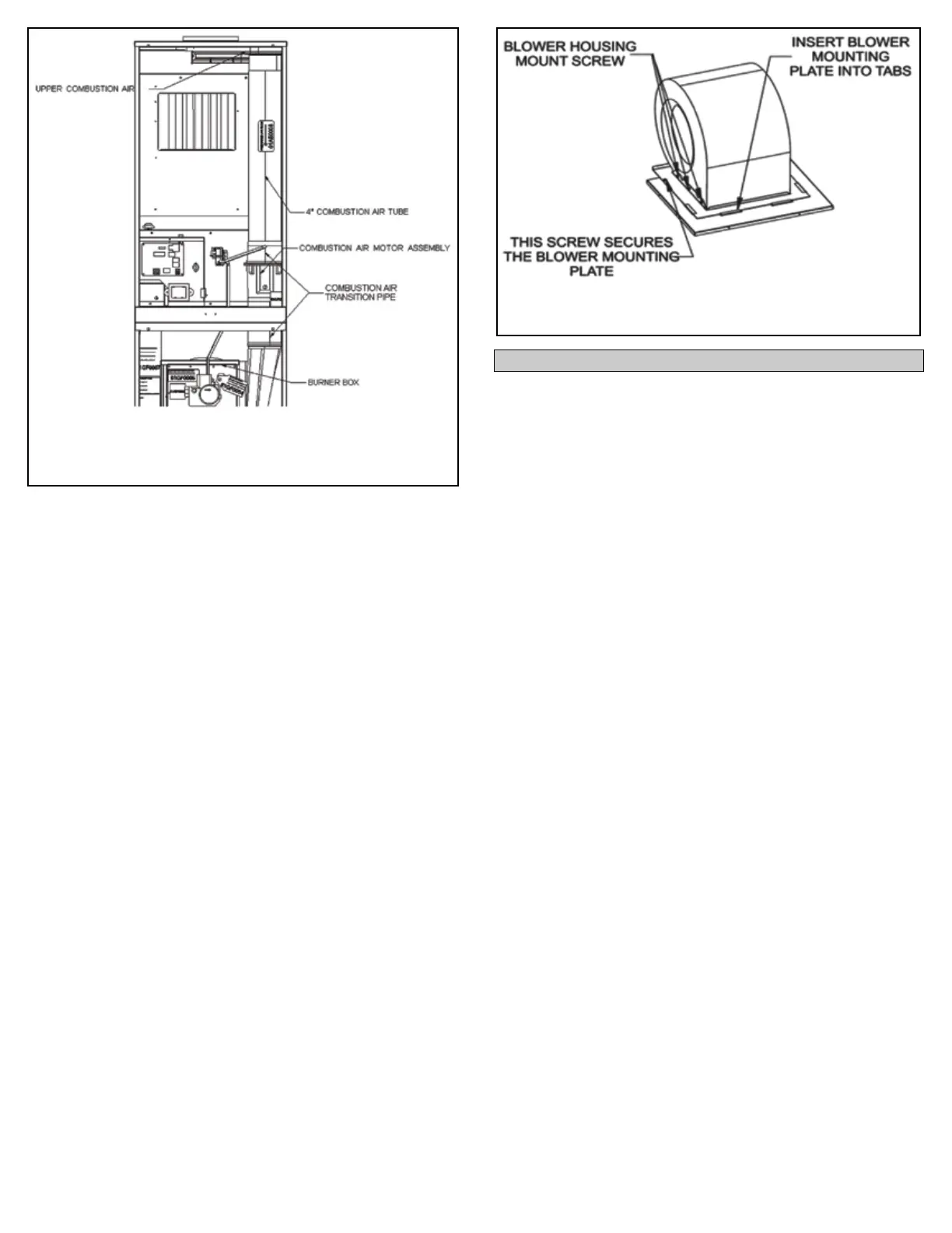
Figure 15: Blower Assembly
6. Remove the 2 screws on the left side of the blower mounting
bracket.
7. Lift the blower upward while moving it to the left and pull the
blower back to remove it.
8. Use a vacuum cleaner and a small brush to remove any dust
and debris from the blower compartment.
9. Check in the area below the blower compartment where the
heater exchanger tubes are located and remove any dust and
debris from around the heat exchanger tubes. Be careful not
to damage the heater exchangers with the vacuum hose or the
brush.
10. Place a piece of cardboard on top of the indoor cooling coil to
collect the dislodged dust and debris and prevent it from
falling on the coil.
11. Check the blower wheel for dust and debris. Use a brush and
vacuum cleaner to remove any dust or debris from the blower
wheel. Be careful not the move or accidentally remove the
balance weight(s) located on the blower wheel blades . If a
weight is moved or removed, the blower wheel will vibrate. If
the blower wheel is vibrating, it must be replaced.
12. Check the blower motor for dust and debris. Clean the
openings in the motor housing as these openings allow air
to enter and cool the motor windings. Dust and debris
blocking these openings will cause the motor to run hotter
than normal and will shorten the life of the motor.
13. Reinstall the blower assembly and secure the assembly using
the screws that were removed in steps 5 and 6.
14. Connect the blower motor wiring harness 6-pin plug to the
mating plug located on the right side of the control box.
15. Reinstall the burner compartment access panel on the front of
the furnace.
16. Reinstall the louvered return air lter door on the front of the
furnace.
17. Follow the instructions in Section 3: Startup and Shutdown
Instructions of the User Information Manual to properly
start the furnace.
The following describes the furnace controls and how they
operate. Refer to Figure 16 for component locations.
1. Limit Switch – An auto-reset over-temperature limit switch is
located on the vestibule panel to sense overheating of the heat
exchangers and its contacts will open if the temperature around
the switch rises above its set-point, shutting down the burner.
2. Manual Reset Limit Switch – A manual reset over-temperature
limit switch is located in the burner compartment to shut the
burner down if the switch contacts open due to overheating in
the blower compartment due to a failed blower motor.
3. Integrated Furnace Control Board – The integrated furnace
control board manages all control functions needed for the
operating of the furnace. The control board provides outputs for
3 speed taps for the circulating blower motor (heating, cooling,
and continuous fan), the induced draft blower, the main gas
valve, and the hot surface igniter. The control board receives
inputs from the thermostat, pressure switch, limit switches, and
ame sensor.
4. Pressure Switch – The pressure switch senses the negative
pressure in the induced draft blower housing and closes its
contacts when the negative pressure reaches the set point of
the switch.
5. Induced Draft Blower Assembly – The induced draft blower
assembly consists of a motor, blower wheel, and =
blower housing and draws the combustion air and by-products
of combustion through the heat exchanger tubes and forces
them up the exhaust vent.
6. 3 Amp Fuse – An automotive type fuse is located on the
integrated furnace control and is used for over-current
protection of the 24 VAC system control circuit.
7. Transformer – The transformer is used to step down voltage
from 115 VAC to 24 VAC and provides the required 24 VAC for
the system control circuit.
SECTION 3: FURNACE CONTROLS