MORTEX PRODUCTS INC 501 TERMINAL RD FORT WORTH, TX 76106 Page 14
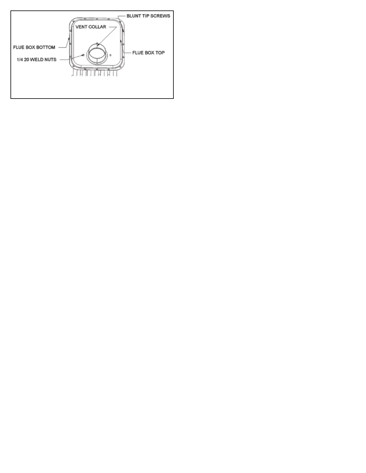
Figure 13: Flue Box Assembly
Cleaning the Combustion Air Assembly
The combustion air assembly should be removed and visually
inspected for dust and debris accumulation during the annual
inspection. If cleaning is required, follow the steps below.
1. Follow the instructions in Section 3: Startup and Shutdown
Instructions of the User Information Manual to properly
shut the furnace o.
2 Remove the louvered return air lter door on the front of the
furnace.
3. Remove the burner compartment access panel on the front of
the furnace.
4. Turn the valve in the gas supply line to the “OFF” position and
loosen the ground union joint (See Figure 5).
5. Remove the gas line from the gas valve. Use a wrench on the
gas valve hub (wrench boss) located on the inlet side of the
gas valve to prevent the gas valve from rotating when the gas
line is being removed.
6. Remove the wires from the gas valve terminals.
7. Unplug the wires from the ame sensor and igniter.
8. Remove the 10 screws from the burner mounting plate and
remove the burner assembly (See Figure 8).
9. Lift the burner assembly and turn it slightly too clear the air
baes and slide the burner assembly back to remove it.
10. Remove the 1/4” tube from the top right side of the burner box.
11. Remove the 4 screws that secure the combustion air baes to
the burner box / vestibule panel (See Figure 14).
12. Remove the 4 remaining screws that secure the burner box to
the vestibule panel. Be careful not to damage the gasket
on the back side of the burner box. If the gasket is damaged,
it must be replaced. A good seal between the burner box and
the vestibule panel is required for the furnace to operate
properly.
13. Remove the 2 Phillips head screws the secure the bottom of
the combustion air assembly to the 4” pipe.
14. Grasp the burner box and twist slightly while pulling down
to remove the 4” pipe from the combustion air housing
(See Figure 14).
15. Unplug the male and female insulated terminals that go to the
combustion air assembly.
16. Remove the 2 screws in the top of the combustion air housing
and remove the assembly from the upper 4” pipe (See Figure 14).
17. Use a soft bristle brush and vacuum cleaner to clean the dust
and debris from the housing, motor and prop fans. Be careful
not to damage the plastic fans. Use the vacuum cleaner when
brushing the pipe and fan to prevent the dust and debris from
entering the motor windings. Dust and debris will cause the
motor to run hotter and will reducing motor’s life.
18. Place the round black gasket on the 4” upper pipe so the pipe
sits inside the grove in the gasket and slide the combustion air
housing into the gasket. Secure the housing to the 4” pipe
with 2 screws removed in step 16. Make sure the gasket is
properly inserted into the pipe so there is a good seal at the
pipe and around the combustion air housing.
19. Place the round black gasket on the 4” lower pipe so that the
pipe sits inside the grove in the gasket and slide the combustion
air housing into the gasket. Secure the housing to the 4” pipe
with the 2 screws removed in step 13. Make sure the gasket is
properly inserted into the pipe so there is a good seal at the
pipe and around the combustion air housing.
20. Place the gasket on the back side of the burner box so it is
between the burner box and the vestibule panel. If the gasket
is damaged, it must be replaced. There must be a good seal
between the burner box and the vestibule panel for the
furnace to operate properly. Install the 4 screws that were
removed in step 11 and tighten until secure.
21. Place the combustion air baes into the burner box and use
the 4 screws that were removed in step 10 to secure the
baes to the burner box.
22. Connect the 1/4” tube to the nipple located on the top right
side of the burner box (See Figure 14).
23. Install the burner assembly and secure the assembly to the
burner box with the 10 screws that were removed in step 8.
24. Connect the 2 white wires to the igniter.
25. Connect the yellow wire to the ame sensor.
26. Connect the brown wires to the gas valve terminals.
27. Connect the gas supply line. It is recommended that a new
pipe that is properly chamfered, reamed, and free of burrs and
chips be installed. If the old pipe is reused, it must be clean
and free of rust, scale, burrs, chips, and old pipe joint compound.
28. Apply pipe joint compound that is approved for all gases only
to the male threads of the pipe joints. Do not apply compound
to the rst two threads nearest the end of the pipe.
29. Use a wrench on the gas valve hub (wrench boss) located on
the inlet side of the gas valve to prevent the gas valve from
rotating when the gas line is being tightened. Do not] over
tighten the gas pipe which will cause damage to the gas valve.
Use a torque wrench to tighten the pipe to a maximum of 375
in-lb. If a torque wrench is not available, tighten the gas pipe
by hand and then turn the pipe an additional ½ - ¾ turn or
until the connection is snug and not leaking.
30. Connect the union joint and tighten the union.
31. Turn the manual gas valve to the “ON” position (See Figure 5).
32. Check the entire gas supply line for leaks.
33. Install the burner compartment access panel on the furnace.
34. Install the louvered return air lter door on the furnace.
35. Follow the instructions in Section 3: Startup and Shutdown
Instructions of the User Information Manual to properly
start this furnace.
Cleaning the Indoor Fan Assembly
1. Follow the instructions in Section 3: Startup and Shutdown
Instructions of the User Information Manual to properly
shut the furnace o.
2. Remove the louvered return air lter door located on the front
of the furnace.
3. Remove the burner compartment access panel located on the
front of the furnace.
4. Unplug the blower motor wiring harness 6-pin plug located on
the right side of the control box.
5. Remove the 2 screws on the right side of the blower mounting
bracket.
 Loading...
