MORTEX PRODUCTS INC 501 TERMINAL RD FORT WORTH, TX 76106 Page 13
Cleaning the Flue Box Assembly
1. Follow the instructions in Section 3: Startup and Shutdown
Instructions of the User Information Manual to properly
shut this furnace down.
2. Remove the louvered return air lter door on the front of the
furnace.
3. Slide the roof jack combustion air and vent piping upward as
far as possible to remove the pipes from the combustion air
and vent anges at the top of the furnace.
4. Remove the 4 screws that secure the blend air adapter to the
top cover if a blend air system is being used.
5. Remove the 11 screws from the furnace top cover.
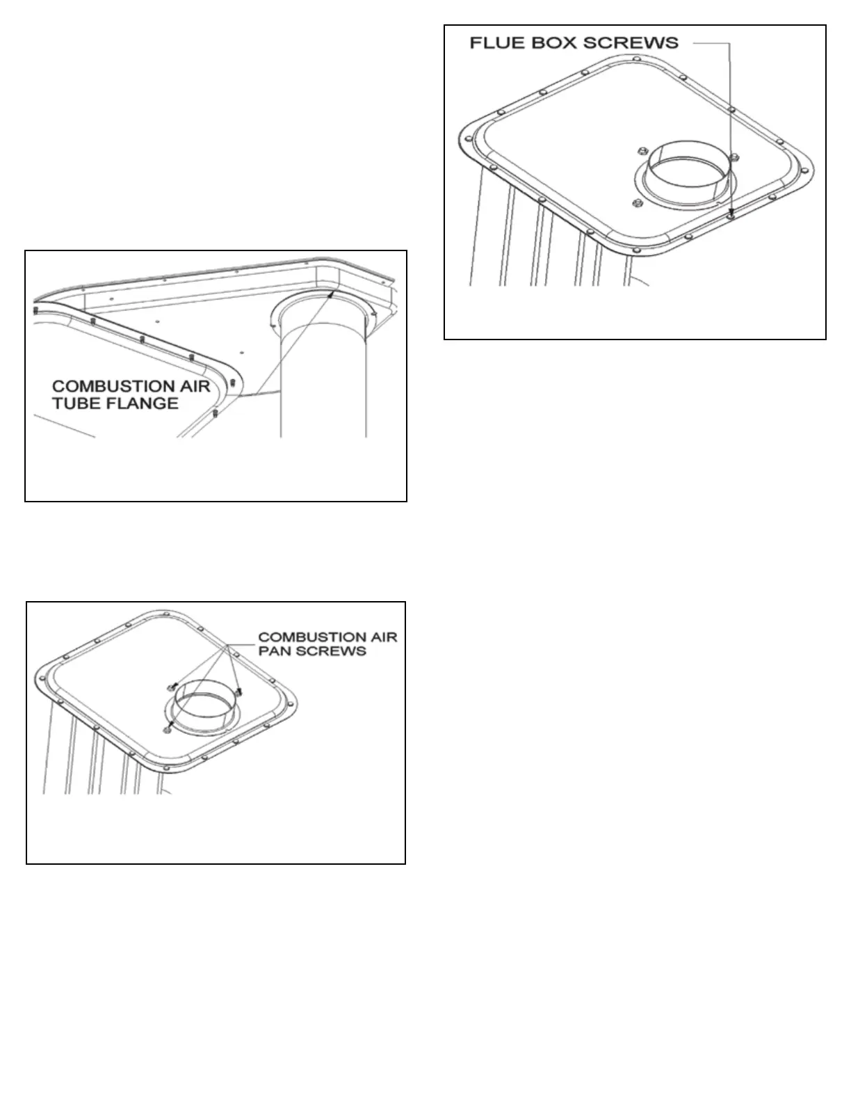
Figure 10: 4” Combustion Air Tube Flange
Figure 12: Flue Box Cover Screws
Figure 11: Top Cover Screws
and Combustion Air Pan Screws
6. Remove the three 1/4”-20 nuts next to the ue collar.
7. Remove the two 3/16”-16 Phillips head screws from the ange
at the top of the 4” combustion air pipe located inside the
blower compartment (See Figure 10).
8. Remove the 3 screws from the combustion pan cover. Refer to
Figure 11.
9. Remove the top cover. Be very careful not to damage the
insulation and the gaskets. If the insulation or the gaskets are
damaged, they must be replaced.
10. Remove the 16 screws from the ue box cover. Do not mix
these screws with the other screws as these are stainless steel
which is required due to the heat and corrosive ue products.
Refer to Figure 12 for screw locations.
11. Remove the ue box cover. Be very careful not to damage
the gasket on the ange. If the gasket is damaged, it must be
replaced.
12. Use a brush and vacuum cleaner to clean the tubes and the
ue box area.
NOTE: Debris removed from the wall of the tubes by the brush
will fall into the base of the heat exchanger. Be sure to vacuum
the base to remove the debris after brushing all of the tubes.
13. Place the ue box cover on top of the ue box base and secure
with the stainless steel screws that were removed in step 9.
NOTE: Inspect the gasket to make sure it is not damaged.
A good seal between the ue box cover and the ue box base
is required for the furnace to operate properly and to prevent
leakage of ue products into the conditioned space. Replace
the gasket if it is damaged.
14. Place the top cover on top of the furnace. Make sure the bolt
holes in the combustion air pan line up with the 1/4”-20 bolts
next to the ue collar.
NOTE: Inspect the gasket between the combustion air pan and
the ue box to make sure it is not damaged. Replace the
gasket if it is damaged. A good seal between the combustion
air pan and the ue box is required for the furnace for the
furnace to operate properly.
15. Install the three 1/4”-20 nuts on the three 3 bolts and tighten
until secure.
16. Install the 11 screws in the top cover and tighten until secure.
Do not over-tighten and strip these screws.
17. Place the blend air bracket over the 4” hole and align the screw
holes. Install the screws to secure it to the top cover. NOTE:
This step is not required if a blend air system is not used.
18. Install the louvered return air lter door on the front of the
furnace.
19. Follow the instructions in Section 3: Startup and Shutdown
Instructions of the User Information Manual to properly
start the furnace.