MORTEX PRODUCTS INC 501 TERMINAL RD FORT WORTH, TX 76106 Page 20
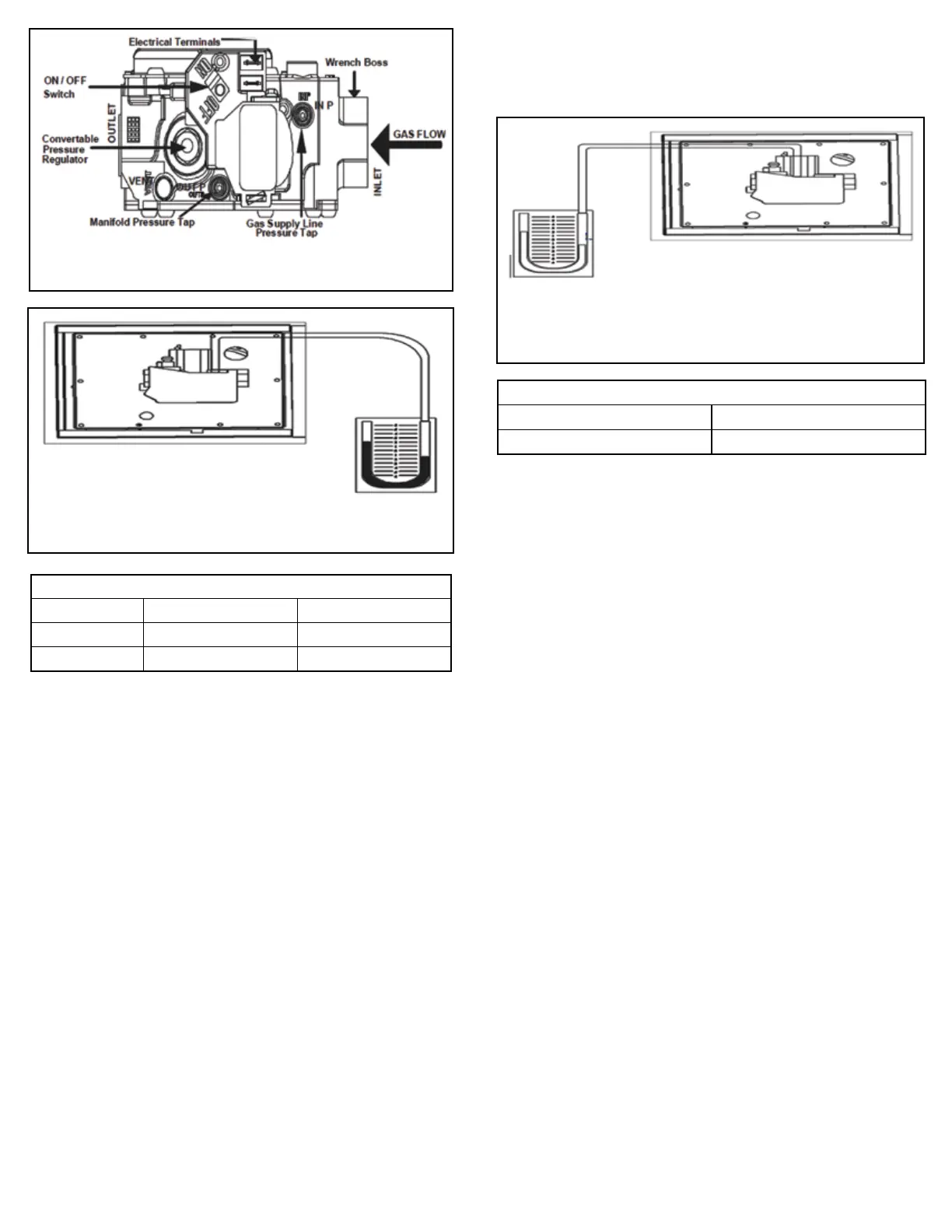
Figure 17: White Rodgers Gas Valve
Figure 18: Measuring Inlet (Supply)
Gas Pressure (IN P)
Figure 19: Measuring Outlet (Manifold)
Gas Pressure (OUT P)
Table 1: Inlet (Supply) Gas Line Pressure Range
Table 2: Nominal Manifold Gas Pressure
INLET GAS PRESSURE RANGE
NATURAL GAS PROPANE (LP)
MINUMUM 4.5” W.C. (1.12 kPa) 11.0” W.C. (2.74 kPa)
MAXIMUM 10.5” W.C. (2.21 kPa) 13.0” W.C. (3.24 kPa)
NOMINAL MANIFOLD PRESSURE
NATURAL GAS 3.5” W.C. (0.87 kPa)
PROPANE (LP) GAS 10.0” W.C. (2.49 kPa)
Checking the Manifold Pressure
1. Find the gas valve pressure ports labeled “OUT P” (See Figure
18). OUT P is the manifold pressure tap.
2. Use a 3/32” (2.4 mm) Allen wrench to loosen the set screw by
turning it counter clockwise one (1) turn only on the “IN P” port.
DO NOT REMOVE THE SET SCREW.
3. Connect the 1/8” (3.175 mm) ID exible tubing to the positive
side of the “U” tube monometer or pressure gauge and the
other end of the tubing to the port marked “IN P” on the gas
valve as shown in Figure 20.
4. Follow the “Starting the Furnace” instructions located in
Section 3: Startup and Shutdown Instructions in the User
Information Manual to properly start the furnace.
5. With the furnace operating, read the manifold pressure. The
pressure should be between 3.3” W.C. and 3.6” W.C. for natural
gas and 9.8” W.C. and 10.2” W.C. for propane (LP). Check the
input using the calculations in Table 3 or Table 4. page. If the
input is not within 8% of the input listed on the furnace data
plate, replace the gas valve.
6. Turn the switch on the gas valve to the “OFF” position.
7. Remove the pressure hose from the pressure port and tighten
the set screw.
8. Follow the “Starting the Furnace” instructions located in
Section 3: Startup and Shutdown Instructions in the User
Information Manual to properly start the furnace.
9. Proceed to Temperature Rise Check and Adjustment.
Checking the Furnace Input Rate
The gas pressure regulator in the combination gas control is
adjusted at the factory for average gas conditions. It is important
that gas be supplied to the furnace in accordance with the input
rating listed on the furnace data plate. Actual input should be
checked and necessary adjustments made after the furnace is
installed. Over-ring, a result of excessive gas input, reduces
the life of the furnace and increases maintenance. Under no
circumstances should the input exceed that shown on the data
plate.
Input can be determined by the meter-timing method as long as
all other gas burning appliances connected to the meter are o
during the test. If this is not possible, use the pressure method.
“IMPORTANT”: Inlet pressure and manifold pressure must
be checked with the furnace operating when making nal
adjustments.
Meter Timing Method
1. Shut o all other gas-burning appliances served by the gas
meter, including those with pilot lights.
2. Start the furnace and determine the number of seconds it
takes to consume 2 cu. ft. or 0.1 cu. meter of natural gas or 1 cu.
ft. or 0.05 cu. meter of propane gas. Refer to Table 3 or Table 4
for the procedure for calculating heating input.
The heating value of gas may be obtained from the local utility or
gas dealer. If the utility or gas dealer does not know the heating
value of the gas you may use the values shown below:
Use 1030 BTU/cu. ft. (38.4 Mj/m³) for natural gas
Use 2500 BTU/cu. ft. (93.15 Mj/m³) for propane gas
BTU/cu. ft. or Mj/m³ = heating value of gas