Cooling Mode Dip Switch Settings (SW1)
Motor Speed Tap Number
T1
Factory Setting
T2 T3 T4
SW1
Dip Switch
Number and
Setting
SW1
Dip Switch
Number and
Setting
SW1
Dip Switch
Number and
Setting
SW1
Dip Switch
Number and
Setting
1 2 3 1 2 3 1 2 3 1 2 3
O
O
O On O O On On O O On O
Heating Mode Dip Switch Settings (SW2)
Motor Speed Tap Number
T1 T2
Factory Setting
T3 T4
SW2
Dip Switch
Number and
Setting
SW2
Dip Switch
Number and
Setting
SW2
Dip Switch
Number and
Setting
SW2
Dip Switch
Number and
Setting
1 2 1 2 1 2 1 2
O
O
On O On On O On
Constant Circulation Dip Switch Settings (SW2)
Motor Speed Tap Number
T1
Factory Setting
T2 T4
SW2
Dip Switch
Number and
Setting
SW2
Dip Switch
Number and
Setting
SW2
Dip Switch
Number and
Setting
3 4 3 4 3 4
O
O
On O O On
Heating Blower O Delay Dip Switch Setting (SW1)
150 Seconds (Factory Setting) 100 Seconds
SW1 Dip Switch Number
and Setting
SW1 Dip Switch Number and
Setting
4 4
On
O
MORTEX PRODUCTS INC 501 TERMINAL RD FORT WORTH, TX 76106 Page 22
9. Disconnect the wires from the motor terminal block.
10. Loosen the set screw on the blower wheel hub that secures
the wheel to the blower motor shaft. Make sure the wheel
spins freely with no obstructions. File o any burrs on the
motor shaft before trying to remove the wheel.
11. Remove the 3 screws that secure the motor mounting bracket
legs to the blower housing and remove the motor from the
blower housing.
12. Note or take a photo of the relative position of the belly
band and motor mounting bracket legs to the motor and
motor terminal block to assure they are positioned correctly
on the new motor.
13. Remove the blower motor from the motor mounting bracket
by removing the screw and nut that secures the belly band
around the blower motor.
14. Insert the new motor into the motor mounting bracket
and secure the bellyband to the motor with the screw and
nut removed in the previous step. Make sure the belly band
and motor mounting bracket legs are positioned in the same
place and orientation as they were on the original motor so
the motor is not at an angle and the wire terminals are located
in the proper position.
15. Secure the motor mounting bracket legs to the blower
housing with the 3 screws removed in step 11. Tighten the
screws until the mounting bracket arms are securely fastened
to the blower housing.
16. Position the blower wheel in the housing until the wheel
is centered between the orices on each side of the housing.
Center the setscrew on the center of the shaft at and tighten
the setscrew securely to hold the wheel in place.
17. Connect the blower motor wires to the correct motor
terminals. If the wires were not labeled from step 8, refer to
the furnace wiring diagram for the correct connections.
18. Reinstall the blower assembly and secure the assembly using
the screws that was removed in steps 5 and 6.
19. Connect the blower motor wire harness 9-pin plug to the
mating plug located on the top right side of the control box.
20. Install the burner compartment access panel on the front of
the furnace.
21. Install the louvered return air lter door on the front of the
furnace.
22. Follow the “Starting the Furnace” instructions in Section 3:
Startup and Shutdown Instructions of the User
Information Manual to properly start the furnace.
23. Set the thermostat to the desired mode and temperature.
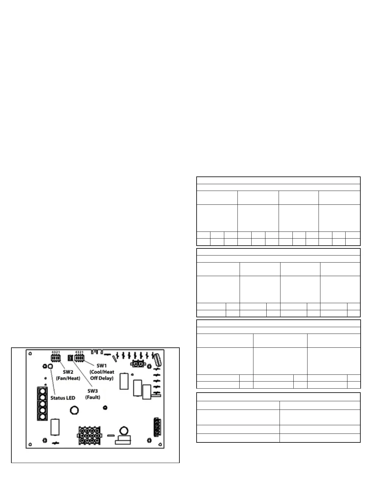
Circulating Blower Motor Speed Taps and Heating Blower O
Delay - Dip Switch Settings
The circulating blower motor speed tap and heating blower o
delay dip switches (SW1 and SW2) are located on the top left
side of the control board (Refer to Figure 21). The motor speed
taps can be selected for the cooling mode, heating mode, and
constant circulation mode by changing the dip switch settings
as shown in Table 5. The heating blower o delay can also be
selected by changing the dip switch setting as shown in Table 5.
The individual dip switches are numbered on each switch body.
Push the dip switch in the direction of the “ON” printed on the
switch body to select “ON” and away from the “ON” printed on the
switch body to select “OFF”. The factory and optional settings are
shown below.
Factory Cooling Speed: T1 (High)
Optional Cooling Speeds: T2 (Medium High) & T3 (Medium)
Factory Heating Speed: T2 (Medium High)
Optional Heating Speed: T3 (Medium)
Factory Constant Circulation Speed: T1 (High)
Optional Constant Circulation Speeds: T2 – T4
Factory Heating Blower O Delay Setting:150 Seconds
Figure 20: Integrated Furnace Control Board
Table 5: Dip Switch Settings For Circulating Blower
Motor Speeds and Heating Blower O Delay