10 Morton
®
Water Softener Installation & Operation Manual
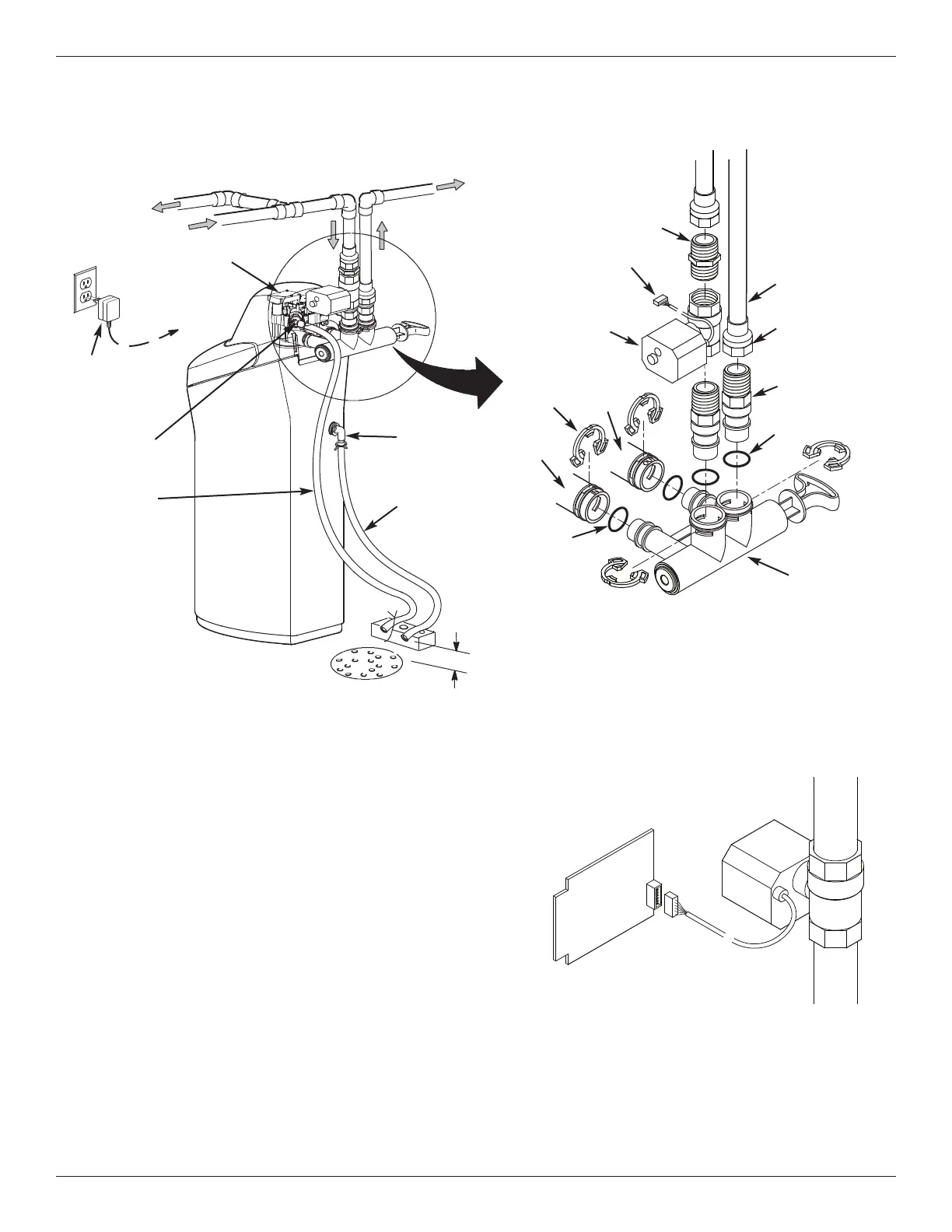
TYPICAL INSTALLATION (with optional motorized water shutoff valve)
FIG. 9B
NOTE: See “Air Gap Requirements” section.
NOTE: Water Softener shown with Salt Lid and
Top Cover removed
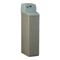
Inlet
Outlet
Clips
Pipe
To Outside
F
aucets
1” NPT Sweat
Adaptor (not
included)
O-ring
Single
Bypass Valve
Lubricated
O-ring
Soft
Water
Hard Water
M
a
i
n
W
a
ter
Pi
p
e
Water Softener
Valve
Valve Drain
Elbow
Valve Drain
Hose*
*Do not connect the
water softener valve drain
tubing to the salt storage
tank overflow hose.
Floor Drain
Overflow
Drain Elbow
Salt Storage
Tank Overflow
Hose*
Secure Valve Drain
Hose in place over
Floor Drain
1” NPT
Threaded
Adaptor
1-1/2”
air gap
Plug-in
Power
Supply
To
Controller
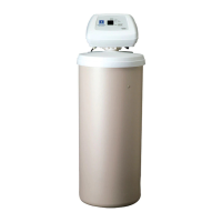
Installation Instructions
Optional Motorized
Water Shutoff Valve
(not included with
water softener)
1” NPT Nipple
(
provided with
optional motorized
water shutoff valve)
Plug into Controller
Optional Motorized
Water Shutoff Valve
Electronic Control
Board on back of
Faceplate
Plug cable into elec-
tronic control board
(power must be off)
FIG. 9C
Step 4. (Optional) Install the Motorized Water Shutoff Valve
If you purchased the optional water shutoff valve,
install it in the plumbing upstream of the softener inlet.
Figure 9B shows installation with the shutoff valve
immediately upstream of the bypass valve inlet, using
one of the softener’s installation adaptors and the 1”
NPT nipple provided with the shutoff valve.
The shutoff valve may also be installed in the plumbing
farther upstream of the softener, making sure that the
10 foot long cable will reach the softener’s electronic
control board (See Figure 9C). The shutoff valve’s
inlet and outlet are female 1” NPT. Support the weight
of the shutoff valve.
After completing plumbing, make sure that the water
softener is not powered up, and plug the cable from
the shutoff valve into the corresponding connector on
the electronic control board (See Fig. 9C or Schematic
on Page 26).
CAUTION: Do not place fingers into the motorized
shutoff valve when it is plugged into the electronic con-
troller.
NOTE: The shutoff valve may be operated manually
by pulling out and turning the knob on the shutoff valve
body (See Fig. 64 on Page 27), although there is no
need to do this when installing.