Home
Motoman
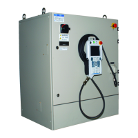
Controller
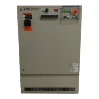
XRC 2001
Motoman XRC 2001 - User Manual
387 pages
Manual
Specs
Ask a question
Save Page as PDF
To Next Page
To Next Page
Loading...
Motoman, Incorporated
805 Liberty Lane
W
est Carrollton, OH 45449
TEL: (937) 847-6200
F
AX: (937) 847-6277
24-Hour Service Hotline: (937) 847-3200
Motoman XRC 2001 Contr
oller
Operator’s Manual
for Spot Welding
Part Number:
142101-1
Release Date:
November 28, 2006
Document Status:
Final
2
Table of Contents
Main Page
Introduction
5
Safety
7
Op for Beginners
13
Table of Contents
19
1 INTRODUCTION
23
1.1 XRC Overview
23
1.2 Button Descriptions
24
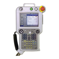
1.3 Programming Pendant
25
1.4 Key Descriptions
26
Named Keys
26
Symbol Keys
26
Axis Keys and Number Keys
26
Simultaneously Pressed Keys
26
1.5 Screen Descriptions
27
1.6 Operation Sequence
28
2 TURNING THE POWER ON
29
2.1 Turning On the Main Power
29
2.1.1 Startup Diagnostics
29
2.1.2 When Startup Diagnostics are Complete
29
2.2 Turning on the Servo Power
30
2.2.1 During Play Mode
30
2.2.2 During Teach Mode
30
3 TEACHING
33
3.1 Manipulator Motion
33
3.1.1 Joint Coordinates
33
3.1.2 Rectangular Coordinates
35
3.1.3 Move Instructions and Steps
36
3.2 Teaching
37
3.2.1 Preparation Before Teaching
37
3.2.2 Teaching
40
Teaching a Job
40
Step 1 -- Start Position
41
Step 2 -- Near the Work Start Location
42
Step 3 -- Work Start Location
42
Step 4 -- Work End Position
43
Step 5 -- Position Away From Workpiece and Fixture
44
Step 6 -- Near the Start Position
45
Ensuring the First and Last Step are Identical
46
3.2.3 Path Confirmation
46
3.2.4 Correcting a Job
47
Before Correcting a Job
47
Change the Position Data
48
Add a Step
48
Delete a Step
49
Changing the Speed Between Steps
50
4 PLAYBACK
51
4.1 Preparation Prior to Playback
51
4.2 Playback
51
5 ARC WELDING
53
5.1 Example Job
53
5.2 Teaching Procedure
53
5.2.1 Teaching Procedure Items
53
5.2.2 Operation Method
54
Step 2 -- Near Welding Start Location
54
Step 3 -- Welding Start Position
54
Step 4 -- Welding End Condition
55
5.3 Setting Welding Conditions
56
5.3.1 Registration of Welding Condition
56
5.3.2 Setting Other Parameters
57
Shielding Gas Flow Rate
57
5.4 Welding Test
58
5.4.1 Check Run
58
5.4.2 Welding Execution
59
5.4.3 Adjustments for Welding Defects
59
6 HANDLING
63
6.1 Example Job
63
6.2 Usage of HAND Instruction
64
6.2.1 Function
64
SP (single-solenoid)
64
2P (double-solenoid)
64
3P (triple solenoid)
64
6.2.2 Instruction and Additional Items
64
6.3 Teaching Procedure
65
6.3.1 Teaching Points
65
6.3.2 Operation Procedure
65
Step 2 -- Near Gripping Position (before gripping)
65
Step 3 -- Gripping Position
66
Step 4 -- Near Gripping Position (after gripping)
67
Step 6 -- Near Release Position (before releasing)
68
Step 7 -- Release Assistance Position
68
Step 8 -- Release Position
69
Step 9 -- Near Release Position (after release)
71
6.4 Handling Test
71
6.4.1 Speed Limitation Drive
71
6.4.2 Handling Execution
72
7 GENERAL PURPOSE
73
7.1 Example Job
73
7.2 Teaching Procedure
73
7.2.1 Teaching Points
73
7.2.2 Operation Procedure
74
Step 2 -- Near cutting position
74
Step 3 -- Cutting Start Position
74
Step 4 -- Cutting End Position
75
7.3 Cutting Test
76
7.3.1 Speed Limitation Drive
76
7.3.2 Cutting Execution
77
8 SPOT WELDING
79
8.1 Example Job
79
8.2 Setting Welding Conditions
80
8.2.1 Setting Spot Welding Gun Condition Files
80
8.2.2 Setting Welding Condition for the Welder
80
8.3 Teaching Procedure
81
8.3.1 Teaching Procedure Items
81
8.3.2 Operation Procedure
81
Step 2 -- Near Welding Start Position
81
Step 3 -- Welding Start Position
82
8.4 Welding Test
83
8.4.1 Check Run
83
8.4.2 Welding Execution
83
9 TURNING THE POWER OFF
85
9.1 Turning the Servo Power Off (Emergency Stop)
85
9.2 Turning the Main Power Off
85
Op for Spot Welding
89
Table of Contents
95
1 An Introduction to XRC
104
1.1 Controller
104
1.2 Playback Panel
105
1.2.1 Playback Panel Overview
105
1.2.2 Button Description
105
1.2.3 Playback Panel Buttons
106
1.3 Programming Pendant
107
1.3.1 Programming Pendant Overview
107
1.3.2 Key Description
108
Character Keys
108
Symbol Keys
108
Axis Keys and Number Keys
108
Keys Pressed Simultaneously
108
1.3.3 Programming Pendant Keys
109
1.3.4 Programming Pendant Display
113
The Four Display Areas
113
Status Display Area
113
Human Interface Display Area
115
1.3.5 Screen Descriptions
115
Denotation
115
Screen
116
1.3.6 Character Input
117
Number Input
117
Letter Input
117
Symbol Input
117
1.4 Modes
118
1.4.1 Operation Mode
118
1.4.2 Operation Location Mode
118
1.4.3 Teach Mode Priority
119
1.4.4 Edit Jobs and Active Jobs
119
1.5 About the Security Mode
120
1.5.1 Types of Security Modes
120
1.5.2 Modifying the Security Mode
123
2 Manipulator Coordinates
126
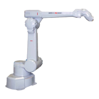
2.1 Robot Axes and Coordinates
126
2.1.1 Types of Coordinates
127
2.2 General Operations
128
2.2.1 Selecting a Coordinate System
128
Motion Type Key
128
2.2.2 Selecting Manual Speed
128
Selecting with Manual Speed Keys
128
Using the High Speed Key
129
2.2.3 Axis Operations
129
Switching the Group Axis to be Operated
129
2.3 Joint Coordinates
130
2.4 Rectangular Coordinates
131
2.5 Cylinder Coordinates
133
2.6 Tool Coordinates
134
2.6.1 Axis Motion
134
2.6.2 Selecting the Tool Number
136
2.7 User Coordinates
137
2.7.1 User Coordinates
137
2.7.2 Examples of User Coordinate Utilization
138
2.7.3 Selecting a User Coordinate Number
139
2.8 Tool Tip Operations
140
2.8.1 TCP Fixed Operations
140
2.8.2 TCP Change Operations
142
3 Teaching
144
3.1 Preparation for Teaching
144
3.1.1 Checking Emergency Stop Buttons
144
3.1.2 Setting the Teach Lock
144
3.1.3 Registering Job Names
145
Characters that Can Be Used in Job Names
145
Registering Job Names
145
3.2 Teaching
146
3.2.1 Teaching Display Screens
146
3.2.2 Motion Type and Play Speed
147
Joint Motion Type
147
Linear Motion Type
148
Circular Motion Type
148
Spline Motion Type
150
3.2.3 Teaching Steps
151
Registering Move Instructions
151
Registering Reference Point Instructions
156
Registering Timer Instructions
157
3.2.4 Overlapping the First and Last Steps
159
3.3 Checking Steps
160
3.3.1 FWD/BWD Key Operations
160
Precautions When Using FWD / BWD Operations
160
Selecting Manual Speed
162
Moving to Reference Point
163
Test Operations
163
3.4 Modifying Steps
165
3.4.1 Displaying the Job Content Display for Editing
168
Currently Called Up Job
168
Calling Up Other Jobs
168
3.4.2 Inserting Move Instructions
169
3.4.3 Deleting Move Instructions
171
3.4.4 Modifying Move Instructions
171
Modifying Position Data
171
Modifying Motion Type
172
3.4.5 Modifying Reference Point Instructions
173
Deleting Reference Point Instructions
173
Modifying Reference Point Instructions
173
3.4.6 Modifying Timer Instructions
174
Deleting Timer Instructions
174
Modifying Timer Instructions
174
3.5 Operations After Teaching
175
3.5.1 Releasing the teach lock
175
4 Playback
176
4.1 Preparation for Playback
176
Calling a Job
176
Registering the Master Job
176
Calling the Master Job
178
4.2 Playback
180
4.2.1 The Playback Display
180
Setting Display or Non-Display of Cycle Time
181
4.2.2 Playback
181
Selecting the start device
181
Selecting Mode
182
Start Operation
182
About the Operation Cycle
182
4.2.3 Special Playback Operations
185
Low Speed Operation
185
Limited Speed Operations
186
Dry Run Speed Operations
186
Machine Lock Operation
187
Check Operation
187
Check Run and Weaving Prohibit
188
Cancel All Special Operations
188
4.3 Stop and Restart
189
4.3.1 Hold
189
Using the Playback Panel
189
Using an External Input Signal (Specific)
189
4.3.2 Emergency Stop
190
4.3.3 Restart After Emergency Stop
192
4.3.4 Stop by Alarm
192
4.3.5 Others
193
Temporary Stop By Mode Change
193
Temporary Stop By the PAUSE Instruction
193
4.4 Modifying Play Speed
193
4.4.1 Modifying With Speed Override
193
Setting Speed Overrides
195
Modifying Play Speed
195
Modifying Speed Override Ratio
196
Releasing Speed Override Settings
196
4.5 Playback With Reserved Start
197
4.5.1 Preparation for Reserved Start
197
Enabling Reserved Start
198
Registering Reserved Start I/O Signal
199
Registering Jobs to Stations
200
Deleting Registered Jobs from Stations
201
4.5.2 Playback from Reserved Start
202
Start Operation
202
Checking Job Reservation Status
203
Resetting Job Reservation
204
4.5.3 Hold Operation
205
[HOLD] on the Playback Panel
205
Hold by External Input Signal (Specific)
205
Hold at the Station
206
4.6 Displaying Job Stack
207
5 Editing
210
5.1 Editing Jobs
210
5.1.1 Displays Related to Job
210
JOB HEADER DISPLAY
210
Job Content Display
211
Command Pos Display
212
Job List Display
212
Job Capacity Display
213
5.1.2 Editing Jobs
214
Copying Jobs
214
Deleting Jobs
216
Modifying Job Names
218
Editing Comments
219
Setting Edit Lock on Individual Job Units
220
Enabling Modification of Position Data Only
221
5.2 Editing Instructions
222
5.2.1 Editing Instructions
222
Instruction Group
223
Inserting Instructions
224
Deleting Instructions
225
Modifying Instructions
225
5.2.2 Editing Additional Items (Line Edit)
227
Modifying Additional Numeric Data
227
Modifying Additional Items
228
Inserting Additional Items
230
Deleting Additional Items
231
5.2.3 Cut and Paste
233
Setting the Range
234
Copying
234
Cutting
235
Pasting
235
Reverse Pasting
236
5.3 Other Editing
237
5.3.1 Editing Play Speed
237
Modification of Speed Type
237
Relative Modification
237
Modification by TRT (Traverse Time)
239
5.3.2 Editing Motion Type
240
5.3.3 Editing Condition Files
241
5.3.4 Editing User Variables
241
Displaying Byte, Integer, Double-Precision, and Real Type Variables
243
Setting Byte, Integer, Double-Precision, and Real Type Variables
244
Registering Variable Name
245
Displaying Position Variables
246
Setting Position Variables
247
Setting Position Variables Using the Number Keys
248
Setting Position Variables Using the Axis Keys
250
Deleting Data Set of Position Variables
251
Checking Positions by Position Variables
251
Manipulator Types
252
5.3.5 Editing Local Variables
256
Setting the Number of Local Variables
257
5.3.6 Searching
258
Line Search
259
Step Search
260
Label Search
260
Instruction Search
261
Tag Search
262
5.4 Setting the Edit Lock
265
5.4.1 Edit Lock For All Jobs (Option)
265
6 Convenient Functions
266
6.1 One-touch Operations
266
6.1.1 Direct Open
266
6.1.2 Reserved Display Call
268
Registering Reserved Displays
269
Calling Reserved Displays
269
6.2 Parallel Shift Function
270
6.2.1 Parallel Shift Function
270
6.2.2 Setting the Shift Value
272
Registering Position Variables
272
Coordinates
272
Setting the Shift Value
273
6.2.3 Registering Shift Instructions
274
SFTON Instruction
275
SFTOF Instruction
276
MSHIFT Instruction
277
6.2.4 Continuation of the Parallel Shift Function
279
6.2.5 Examples of Use
280
Example of Use of Shift Addition/Subtraction
280
Example of Use of MSHIFT Instruction
281
6.3 Parallel Shift Job Conversion Function
282
6.3.1 Parallel Shift Job Conversion
282
Coordinates for Conversion
282
6.3.2 Operating Methods
287
Specifying the Conversion Items
287
Specifying the Shifting Amount
288
Executing Conversion
290
6.4 PAM Function
291
6.4.1 PAM Function
291
Input Ranges for Adjustment Data
291
6.4.2 Operating Methods
292
Setting Adjustment Data
292
Executing the Adjustment
293
Editing Data
294
6.5 Mirror Shift Function
296
6.5.1 Mirror Shift
296
Object Job
296
Group Axes Which Become Objects
296
Position Variable
297
Parameter
297
6.5.2 Operation Method
297
Converting
297
7 Controlling Peripheral Devices
300
7.1 Floppy Disk Unit
300
7.1.1 Floppy Disk Unit
300
Notes on the Use of Floppy Disks and Disk Units
301
Connecting Cables
301
Inserting a Floppy Disk
303
7.1.2 File Management
304
Data That Can Be Saved and Save Destination File Names
305
Selecting a Memory Unit
308
Formatting a Floppy Disk
309
Loading
310
Saving
313
Verifying Data
319
Deleting Files
323
Job Selection Mode
325
How to Select Job and Data Files
327
8 OVERVIEW OF THE SPOTWELDING SYSTEM
328
9 SPECIFIC KEYS
330
10 TEACHING
332
10.1 Manual Spot Welding Function
332
10.1.1 Spot Welding
332
10.1.2 Dry Spotting
332
10.1.3 Stroke Switching
333
10.1.4 Welding On/Off
333
10.1.5 Resetting Alarms
333
10.2 Registering Work Instructions
334
10.2.1 GUNCL Instruction
334
Additional items
335
Operation
335
Examples
335
10.2.2 SPOT Instruction
336
Additional items
336
Operation
337
Examples
337
10.2.3 STROKE Instruction
338
Additional items
338
Operation
339
Examples
339
10.2.4 STRWAIT Instruction
339
Additional items
339
Operation
340
Examples
340
11 Setting the Welding Condition
342
11.1 Manual Spot Display
342
11.2 Spot Welder Condition Data File
344
11.3 Spot Gun Condition Data File
347
12 SPOT WELDING DIAGNOSIS
350
12.1 Spot Welding Diagnosis Display
350
Tip Hit Count Clear
351
13 SPOT GUN MOTION CONTROL
352
13.1 Gun Motion Control
353
X type gun
353
C type gun
354
13.2 Process Timing
355
13.2.1 OPERATION MODE = 0 (SINGLE GUN, OPEN -> WELDING -> OPEN)
355
Gun Motion Control (With X gun, C gun, single type)
355
13.2.2 OPERATION MODE = 1(SHORT OPEN -> WELDING -> SHORT OPEN)
356
Gun Motion Control (With C gun double stroe) (With X gun double stroke, cylinder type)
356
Gun Motion Control (With X gun double stroke, mechanical stopper type)
356
13.2.3 OPERATION MODE = 2(SHORT OPEN -> WELDING -> FULL OPEN)
357
Gun Motion Control (With C gun double stroke)(With X gun double stroke, cylinder type)
357
Gun Motion Control (With X gun double stroke, mechanical stopper type)
357
13.2.4 OPERATION MODE = 3(FULL OPEN -> WELDING -> SHORT OPEN)
358
Gun Motion Control (With C gun double stroke)(With X gun double stroke , cylinder type)
358
Gun Motion Control (With X gun double stroke, mechanical stopper type)
358
13.2.5 OPERATION MODE = 4(FULL OPEN -> WELDING -> FULL OPEN)
359
Gun Motion Control (With C gun double stroke) (With X gun double stroke, cylinder type)
359
Gun Motion Control (With X gun double stroke, mechanical stopper type)
359
13.3 Stroke Change Control Method
360
13.3.1 Single gun, C double gun, X double cylinder gun
360
13.3.2 X Double Mechanical Stopper Type
360
When OPEN (SHORT) is specified
360
13.3.3 When FULL OPEN(LONG) is specified
361
14 I/O SIGNALS
362
14.1 I/O Signal Diagram
362
14.2 I/O Allocation Operation
363
Input Allocation Display
363
Output Allocation Display
364
Pseudo Input Signal Display
365
14.3 Allocation Signal Meaning
366
14.4 Spot Welding
368
14.5 Spot Welding Specific Signal Allocation List
369
15 Spot Instructions
374
15.1 Table of Work Instructions
374
11 Table of Basic Instructions
376
Other manuals for Motoman XRC 2001
Manual
38 pages
Concurrent I/O And Parameter Manual
321 pages
Instructions
30 pages
Need help?
Do you have a question about the Motoman XRC 2001 and is the answer not in the manual?
Ask a question
Motoman XRC 2001 Specifications
Print Specification
General
Series
XRC
Model
XRC 2001
Communication Interface
RS-232C, Ethernet (optional)
Programming Method
Teach pendant
Humidity
20% to 80% (non-condensing)
Related product manuals
Motoman XRC
20 pages
Motoman XRC Series
50 pages
Motoman NX100
34 pages
Motoman DX100
270 pages
Motoman PX2850
611 pages
Motoman NX 100
116 pages
Motoman EA1900N
80 pages