The MOTOMAN XRC is an industrial robot system designed for various automated tasks, offering a comprehensive set of features for programming, operation, and maintenance. This manual, specifically the "MAINTENANCE MANUAL Alarm • Error List," focuses on troubleshooting and resolving issues that may arise during the robot's operation.
Function Description:
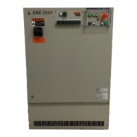
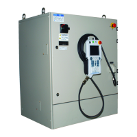
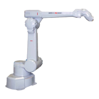
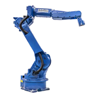
The MOTOMAN XRC system comprises a manipulator (the industrial robot itself), a controller (XRC), a playback panel (P-Panel), a programming pendant (P-Pendant), and supply cables. Its primary function is to execute automated tasks in an industrial environment, ranging from basic programming to complex operations. The system is designed to be integrated into larger machinery or assembled with other equipment to form a complete automated system, adhering to EC Machinery, EMC, and LVD Directives.
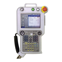
The controller, XRC, serves as the central processing unit, managing all robot movements, program execution, and communication with peripheral devices. The playback panel (P-Panel) provides essential controls for operating the robot in PLAY-mode, including emergency stop functions. The programming pendant (P-Pendant) is a handheld device used for teaching, programming, and detailed system configuration. It features character keys for inputting commands, symbol keys for specific functions, axis keys for robot manipulation, and a display for viewing menus and messages.
The system supports various operational modes, including TEACH mode for programming and PLAY mode for automatic operation. It is equipped with an alarm and error reporting system that categorizes issues by severity (levels 0-9) and provides specific messages, causes, and remedies to facilitate troubleshooting.
Usage Features:
The MOTOMAN XRC is designed for user-friendly operation, with clear guidelines for both programming and automatic execution.
- Programming Pendant (P-Pendant) Operation: The P-Pendant is the primary interface for teaching the robot. Key operations are clearly defined:
- Character keys: Used for alphanumeric input, denoted by
[] (e.g., [ENTER]).
- Symbol keys: Depicted by small pictures (e.g., page key).
- Axis keys/Number keys: Generic terms for controlling robot axes and inputting numerical data.
- Simultaneous key presses: Indicated by a
+ sign (e.g., [SHIFT]+[COORD]).
- Displays: Menu items are shown in italic font (e.g., JOB).
- Playback Panel (P-Panel) Operation: Buttons on the P-Panel are enclosed in brackets (e.g.,
[TEACH]). This panel is crucial for initiating and stopping operations in PLAY-mode.
- Safety Protocols: Emphasized throughout the manual, safety is paramount. Users are instructed to:
- Verify servo power is off when emergency stop buttons are pressed.
- Set the Teach Lock before entering the robot work envelope for teaching.
- Confirm no personnel are in the robot's work area before powering on, moving the robot, or running operations.
- Always return the programming pendant to its hook after use to prevent damage.
- Alarm and Error Handling: The system provides a structured approach to alarms and errors:
- Alarm Levels: Alarms are classified into levels 0-9. Levels 0-3 (major alarms) interrupt servo power and often require turning off and on the main power supply for reset. Levels 4-9 (minor alarms) can typically be reset via the
[RESET] button on the alarm display or a specific I/O signal.
- Alarm Messages: Each alarm has a unique code, message, cause, and recommended remedy, aiding in quick diagnosis and resolution.
- Data Preservation: The JANCD-XCP01 circuit board, which backs up important user program data with a battery, requires careful handling during repairs to prevent data loss. Users are advised to consult MOTOMAN service for repairs involving this board.
Maintenance Features:
The manual provides extensive details on diagnosing and resolving various system issues, particularly focusing on alarms and errors.
-
Reference List: Key manuals for operation, basic programming, installation, and wiring are referenced, providing a comprehensive resource for maintenance personnel.
-
Revision Information: The manual includes a revision history, indicating updates such as new company names and added alarms, ensuring users have access to the latest information.
-
Troubleshooting Alarms (0010-0999): This section details common alarms related to hardware and communication:
- CPU BOARD INSERTION ERROR (0010): Indicates improper circuit board insertion or a defective board. Remedies include checking insertion and replacing the board. Decimal data helps identify the specific XCP02 circuit board (main, sub-board1, sub-board2) or WRCA01 circuit board (for multi-robot systems).
- CPU COMMUNICATION ERROR (0020): Similar to 0010, but specifically for communication errors within the CPU rack. Remedies involve checking board insertion and replacement.
- COMMUNICATION ERROR (SERVO) (0021): Relates to issues with the communication cable for the servopack. Remedies include checking cable connections (XCP01-CN05 to WRCA(#*)-CN10), replacing connectors, or replacing the circuit board. It also checks the rotary switch setting on the WRCA01 board.
- ROM ERROR (0030): Indicates a sum check error in the system program, often requiring circuit board replacement (XCP01, XSP01, XCP02, WRCA01). Consultation with MOTOMAN service is recommended for XCP01 replacement.
- MEMORY ERROR (CPU BOARD RAM) (0040): Points to a RAM error on various circuit boards. Remedies involve replacing the affected board and consulting MOTOMAN service for XCP01.
- MEMORY ERROR (PCI-BUS COMMON RAM) (0050): Signifies an error in the PCI bus shared RAM within the CPU rack or between circuit boards, requiring circuit board replacement.
- COMMUNICATION ERROR (I/O MODULE) (0060): Deals with communication issues or defective I/O modules. Remedies include checking communication cable connections (XCP01-CN01 to XIU01-CN03, WRCA01(#*)-CN20 to XIU01-CN21), replacing connectors, or replacing the I/O module. It also checks the rotary switch setting on the WRCA01 board.
- MEMORY ERROR (PARAMETER FILE) (0200): Occurs when the parameter file is damaged. Remedies include initializing the parameter file in maintenance mode and loading a saved parameter file from an external memory unit.
- MEMORY ERROR (SYSTEM CONFIG-DATA) (0210): Indicates damage to system configuration data, requiring investigation and consultation with MOTOMAN service.
- MEMORY ERROR (JOB MNG DATA) (0220): Signifies damage to job control data. Remedies include initializing the job in maintenance mode (which deletes all job data) and loading saved job data from an external memory unit.
- MEMORY ERROR (LADDER PRG FILE) (0230): Indicates damage to the concurrent I/O ladder program. Remedies include initializing the ladder program in maintenance mode and loading a saved ladder program from an external memory unit.
- VERIFY ERROR (SYSTEM CONFIG-DATA) (0300): Occurs when system parameters are illegally modified, requiring investigation and consultation with MOTOMAN service.
- VERIFY ERROR (CMOS MEMORY SIZE) (0310): Indicates a discrepancy in CMOS memory capacity settings, requiring a check of the XMM01 CMOS memory circuit board for expansion.
- VERIFY ERROR (I/O MODULE) (0320): Occurs when the I/O module status during system initialization or modification differs from the current state. Remedies include verifying the I/O module matches the initialized/modified state and modifying it in maintenance mode.
- VERIFY ERROR (APPLICATION) (0330): Indicates a mismatch between application settings and AP parameters, requiring adjustment of the AP parameter.
- VERIFY ERROR (SENSOR FUNCTION) (0340): Occurs when sensor function settings differ from the sensor circuit board or SE parameters. Remedies include setting the sensor function in maintenance mode or changing the SE parameter.
- PARAMETER TRANSMISSION ERROR (0400): Similar to communication errors, this alarm relates to issues in transmitting parameters to the servopack. Remedies involve checking communication cable connections (XCP01-CN05 to WRCA(#*)-CN10), replacing connectors, or replacing the circuit board. It also checks the rotary switch setting on the WRCA01 board.
- MODE CHANGE ERROR (0410): Occurs during the transition to normal operation mode, often due to issues with circuit board insertion or communication. Remedies include re-inserting the circuit board, replacing it, or checking servopack communication cables and connectors.
- SEGMENT PROC NOT READY (0500): Indicates a communication error between the XCP01 and WRCA01 circuit boards. The remedy is to power cycle the system and contact MOTOMAN service if the error persists.
- WATCHDOG TIMER ERROR (XCP01/XCP02#1/XCP02#2) (0900, 0901, 0902): These alarms indicate insertion errors or defective watchdog timer circuit boards (XCP01, XCP02#1, XCP02#2). Remedies include re-inserting the board, replacing it, and contacting MOTOMAN service if the error persists.
- CPU ERROR (XCP01/XCP02#1/XCP02#2) (0910, 0911, 0912): These alarms point to insertion errors or defective CPU circuit boards. Remedies involve re-inserting the board, replacing it, and contacting MOTOMAN service if the error persists.
- BUS ERROR (XCP01/XCP02#1/XCP02#2) (0920, 0921, 0922): These alarms indicate insertion errors or defective bus circuit boards. Remedies involve re-inserting the board, replacing it, and contacting MOTOMAN service if the error persists.
- CPU HANG UP ERROR (XCP01) (0930): Indicates an insertion error or defective XCP01 CPU circuit board, leading to a CPU hang-up. Remedies involve re-inserting the board, replacing it, and contacting MOTOMAN service if the error persists.
-
General Maintenance Advice:
- Regular inspections are recommended, including checking robot movement and external wire insulation.
- Only original spare parts should be used to maintain warranty validity.
- Unauthorized modifications void the product's warranty.
- MOTOMAN may modify models without notice for product improvements, with corresponding manual revisions.
This comprehensive approach to alarms and errors ensures that maintenance personnel can efficiently diagnose and resolve issues, minimizing downtime and maintaining the operational integrity of the MOTOMAN XRC system.