FR
16
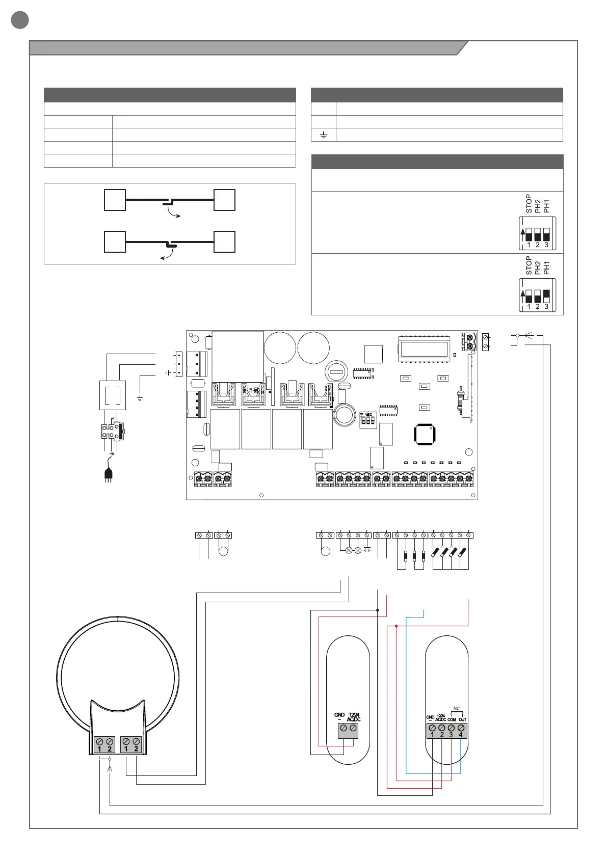
BRANCHEMENT MOTEURS
Bornier des branchements d’alimentation
M1 + Alimentation moteur M1 +
M1 - Alimentation moteur M1 -
M2 + Alimentation moteur M2 +
M2 - Alimentation moteur M2 -
CONNECTEUR ALIMENTATIONS
L Phase alimentation 230 Vac (120 Vac) 50-60 Hz
N Neutre alimentation 230 Vac (120 Vac) 50-60 Hz
Terre
ATTENTION - Avant d’eectuer les branchements, vérier que la logique de commande n’est pas sous tension.
4.5 - Branchements électriques
M1
M1
M2
M2
N
T1,6A
L
230Vac
50/60Hz
PHOTOTEST
OUTPUT LED
OPEN
PHOTOCELL 1
PHOTOCELL 2
CLOSE
PEDESTRIAN
STEP BY STEP
COMMON
STOP/EDGE
INDICATOR
NEGATIVE
24 VAC
24 VAC
M1 M2
FLASH
COM
24 VAC
24 VAC
M1+
M1-
M2+
M2-
COM
FLASH
IND ELEC
LED
NEG
PH POW
STOP
STOP
PH2
PH1
OPEN
CLOSE
SBS
PED
COM
BATTERY
SHIELD
ANT
POWER
SUPPLY
UP
+
-
MENU
SBS
DOWN
(RADIO)
COMMON
FLASH
SHIELD
ANT
COMMON
FLASH
PH1
RX
2
1
PH1
TX
SÉLECTEUR COMMUTATEUR DIP
Sur ON, il désactive les entrées STOP, PH1, PH2
Évite de devoir shunter les entrées sur le bornier.
ATTENTION - Avec le commutateur DIP sur
ON, les dispositifs de sécurité raccordés
sont exclus
ON
OFF
EXEMPLE : Avec une seule photocellule
connectée, réglez STOP et PH2 sur ON
ON
OFF