The MC52 is a single-phase control board designed for the automation of swing gates, suitable for both residential and industrial applications. This user and installer manual provides comprehensive details for its setup, programming, and troubleshooting.
Function Description
The MC52 control board is the central unit for operating swing gates. It manages the opening and closing cycles, integrates safety features, and allows for remote control operation. The system supports two motors, enabling the automation of double-leaf gates. It features various programming options to customize gate behavior, including opening and closing times, force adjustments, and pedestrian access modes. The board also incorporates a radio receiver for remote controls and supports external safety devices like photocells and pushbuttons.
Important Technical Specifications
The MC52 control board is designed for a 230V/50Hz power supply, with a 110V/60Hz version also available.
- Power Supply:
- 110Vac 60Hz
- 230Vac 50-60Hz
- Flashing Light's Output:
- 110Vac 60Hz 500W max.
- 230Vac 50Hz 500W max.
- RGB Flashing Light's Output: 24Vdc 100mA max.
- Motor's Output:
- 110Vac 60Hz 500W max.
- 230Vac 50-60Hz 500W max.
- Auxiliary Accessories Output: 24Vdc 8W max.
- Security and BT Remote Controls: 24Vdc
- Working Temperature: -25°C to +55°C
- Incorporated Radio Receptor: 433.92 MHz
- OP Remote Controls: 12bits or Rolling Code
- Maximum Memory Capacity: 100 (full opening) - 100 (pedestrian opening)
- Control Board Dimensions: 125mm x 140mm
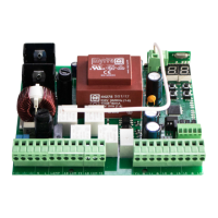
The board includes various connectors for different functionalities:
- CN1 (Power Supply & Motor Connections):
- Grounding connection
- Neutral (N) line input
- Phase (L) line input
- Flashing Light Output (110/230Vac 500W)
- Motor 1 Output (Opening - 110/230Vac 500W, Closing - 110/230Vac 500W, Common - 110/230Vac 500W)
- Motor 2 Output (Opening - 110/230Vac 500W, Closing - 110/230Vac 500W, Common - 110/230Vac 500W)
- 24Vdc 200mA max. Power supply
- Electric lock output (12/24Vdc 15W)
- CN2 (Safety & Control Inputs):
- Total pushbutton input (NA)
- Pedestrian pushbutton input (NA)
- Photocells 1 (NC)
- Photocells 2 (NC)
- Antenna
- GND
- CN3 (Output & Auxiliary):
- Output R (GND)
- Output S (GND)
- Output G (GND)
- Auxiliary output for flashing light or 24Vdc LED
The board features LEDs (V+, LO, LS, LE, LA) to indicate the status of various inputs and operations, aiding in installation and troubleshooting.
Usage Features
The MC52 offers extensive programming options through its P and E menus, allowing users to tailor the gate's operation to specific needs.
- P0 (Course Programming): Defines the gate's opening and closing limits.
- P1 (Deceleration Time Adjustment): Sets the deceleration time for the gate leaves.
- P2 (Force Adjustment): Adjusts the motor force during operation.
- P3 (Pedestrian Course Time): Configures the opening time for pedestrian access.
- P4 (Pause Time and Gates Delay): Sets the pause time before closing and the delay between gate leaves.
- P5 (Photocells 1 Programming): Configures the behavior of the first set of photocells.
- P6 (Photocells 2 Programming): Configures the behavior of the second set of photocells.
- P7 (Operating Logic): Defines the overall operating mode (Automatic, Step by step, Condominium).
- P8 (Flashing Light): Configures the flashing light's operation.
- P9 (Remote Programming): Manages remote control programming.
- E0 (Present Man): Enables or disables the present man function.
- E1 (Soft Start): Activates or deactivates the soft start function.
- E2 (Courtesy Light Time): Sets the duration for the courtesy light.
- E3 (Follow Me): Configures the "Follow Me" function, which allows the gate to close automatically after a safety device detects an object/user.
- E4 (Course Time Adjustment): Fine-tunes the opening and closing course times for each leaf.
- E5 (Brake/Lock/Push): Adjusts electronic brake, lock's operating mode, and pushbuttons.
- E6 (Deceleration Speed): Sets the deceleration speed.
- E7 (Maneuvers Counter): Displays the total number of maneuvers performed.
- E8 (Reset - Restore Factory Settings): Resets all settings to factory defaults.
- E9 (RGB Output): Sets the operation mode of RGB outputs.
Remote Control Programming:
The system supports programming up to 100 remote controls for full opening and 100 for pedestrian opening. Remote controls can be easily added or deleted.
Installation:
The manual provides a detailed installation map and base installation process, including connecting all accessories, power supply, and checking gate movement. It emphasizes the importance of safety instructions and proper wiring.
Display Indications:
The 7-segment display shows various statuses:
8.8: In stop position, fully opened8.8: In stop position, middle position8.8: In stop position, fully closedLO: Total opening button pressedLS: Pedestrian opening button pressedOP: Control board performs opening courseCL: Control board performs closing courseFO: End of opening course timeFC: End of closing course timeLU: All remote controls deleted00 01 02: Remote control added in the indicated positionLE: Obstructed photocellLA: Obstructed photocellRF: In pause timeAP: In pedestrian pause time
Maintenance Features
The manual includes a comprehensive troubleshooting section for both final consumers and specialized installers. This section categorizes anomalies by behavior and provides corresponding procedures for diagnosis and resolution.
Troubleshooting for Final Consumers:
- Motor doesn't work: Check power supply, remote control, and gate movement.
- Motor doesn't move but makes noise: Check gate movement, mechanical problems, and capacitors.
- Motors open but doesn't close: Check remote control, photocells, and safety devices.
- Motor doesn't make complete course: Check gate movement, mechanical problems, and capacitors.
Troubleshooting for Technicians:
For each anomaly, the manual provides detailed procedures for technicians, including:
- Open control board and check if it has 230V power supply.
- Check input fuses.
- Disconnect motors from control board and test them by connecting directly to power supply.
- If motors don't work, the problem is on the control board. Pull it out and send it to our MOTORLINE technical services for diagnosis.
- Remove them from installation site and send to our MOTORLINE technical services for diagnosis.
- Check all motor axis and associated motion systems related with the gate and automatisms (rails, pulleys, bolts, hinges, etc.) to find what is the problem.
- Check capacitors, testing motor with new capacitors.
- If capacitors are not the problem, disconnect motors.
- Check if there is any obstacle in front of the photocells.
- Check if any of the control board LEDs (e.g., selector, pushbutton, video intercom, etc.) are stucked and sending an open signal to control board.
- Consult a qualified MOTORLINE technician.
- All control boards MOTORLINE have LEDs that easily show how to conclude which devices are with anomalies. For example, if a photocell(s) in normal situations remain ON, "START" circuit LEDs in normal situations remain OFF, "F-LETS" circuit LEDs in normal situations remain OFF, "SAFETY" circuit LEDs (photocells, safety edges), if "START" circuits LEDs are turn OFF but the gate or control device sending permanent signal.
- Close with a shunt all safety systems on the control board (check manual of the control board in question). If the automated system begins to work normally check for a problematic device.
- Remove one shunt at a time until you find the malfunction device.
- Replace it for a functional device and check if the motor works correctly with all the other devices. If you find another one defective, follow the same steps until you find all problems.
- Disconnect all wires connected to the START connector.
- If the LED turned OFF, try reconnecting one device at a time until you find the defective device.
- Appropriate force (consult control board manual).
- If this doesn't work, remove control board and send it to MOTORLINE technical services.
- Setting force of the control board should be sufficient to make the gate work without stopping, but should stop and invert with a little effort from a person in case of obstructions/failure, the gate shall never cause physical damage to obstacles (vehicles, people, etc.).
Components Test (Motor A 230V/110V):
The manual provides instructions for testing the motor and capacitor connections, ensuring proper functionality. It emphasizes that all tests must be performed by qualified personnel due to serious danger associated with the misuse of electrical systems.