4A 4B
N L
1 2 3 4 5
COMABLAMP FE
6 7 8 9 10
11 12 13
COMAB FE
L+V+
LO
14 15 16 17 18
LELS LA
ANT
19 20 21 22 23 24 25
V+
LO LS LE LA
B GRY V+
26 27 28 29 30
ENEN
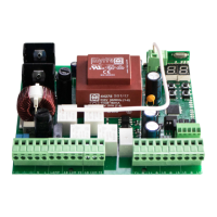
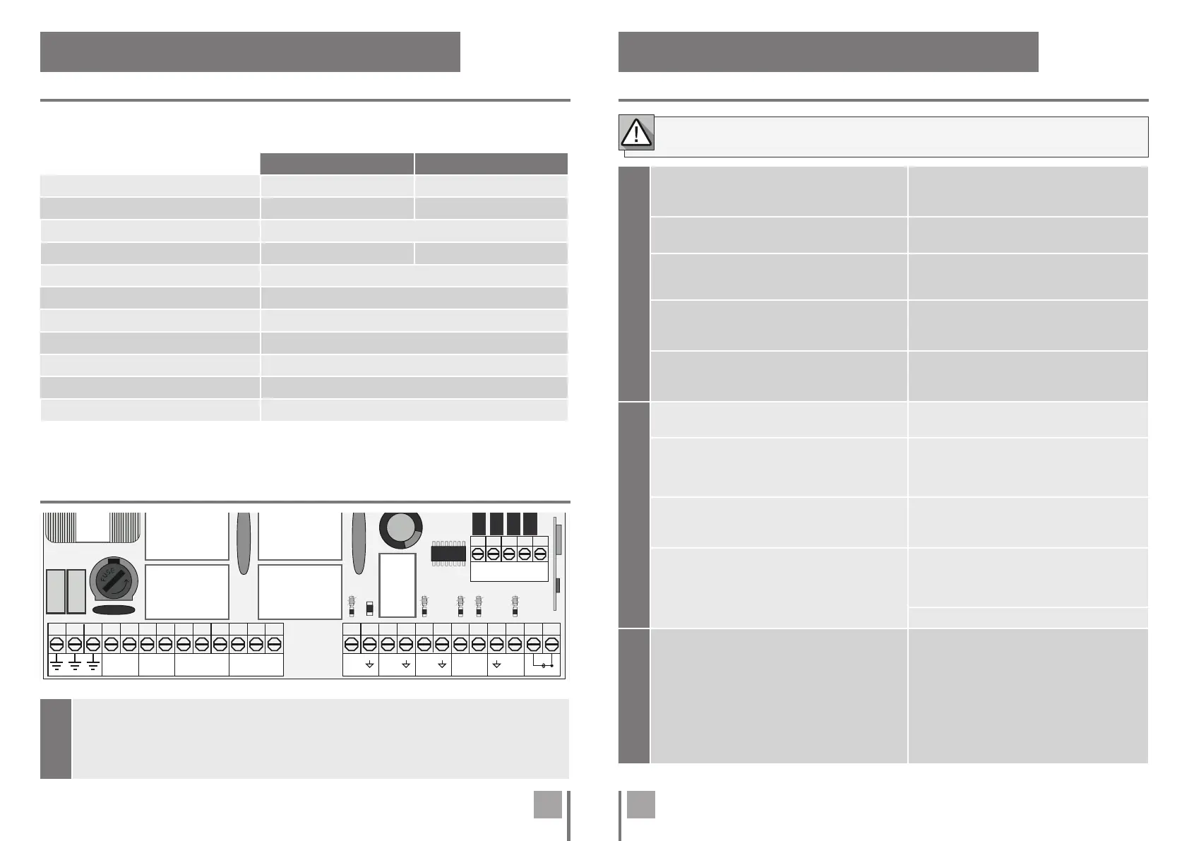
02. CONTROL BOARD 02. CONTROL BOARD
TECHNICAL SPECIFICATIONS
LEDs
CONNECTORS
The MC52 is a single-phase control board with built-in radio control system designed for the
automation of swing gates.
LEDs
V+ • LED On indicates that the line for V+ output is OK.
LS • LED On when pedestrian opening is active.
LO • LED On when full opening is active.
LA • LED on when the photocell is active (P6 active) or the ↓ LA circuit is closed.
LE • LED on when the photocells are active (P5 active) or the ↓ LE circuit is closed.
110V version 230V version
• Power Supply 110Vac 60Hz 230Vac 50-60Hz
• Flashing light’s output 110Vac 60Hz 500W max. 230Vac 50Hz 500W max.
• RGB Flashing light’s output 24Vdc 100mA max.
• Motor’s output 110Vac 60Hz 500W max. 230Vac 50-60Hz 500W max.
• Auxiliary accessories output 24Vdc 8W max.
• Security and BT Remote controls 24Vdc
• Working temperature -25°C to +55°C
• Incorporated Radio Receptor 433,92 Mhz
• OP Remote controls 12bits or Rolling Code
• Maximum Memory Capacity 100 (full opening) - 100 (pedestrian opening)
• Control board Dimensions 125mm x 140mm
Make sure which version you are using (110Vac or 230Vac).
CN1
01 • Grounding connection
02 • Grounding connection
03 • Grounding connection
04 • 110/230Vac (Neutral) (N) line input
05 • 110/230Vac (Phase) (L) line input
110/230Vac Power Supply
06 • Flashing light Output - 110/230Vac 500W
07 • Flashing light Output - 110/230Vac 500W
Courtesy light or Flashing light: This output
allows the connection of a courtesy light or a
Flashing light.
08 • Motor 1 Output - Opening - 110/230Vac 500W
09 • Motor 1 Output - Common - 110/230Vac 500W
10 • Motor 1 Output - Closing - 110/230Vac 500W
Motor 1
11 • Motor 2 Output - Opening - 110/230Vac 500W
12 • Motor 2 Output - Common - 110/230Vac 500W
13 • Motor 2 Output - Closing - 110/230Vac 500W
Motor 2
CN2
14 •
24Vdc 200mA max. Power supply
15 •
24Vdc 200mA max. Power supply
24Vdc Auxiliary Power Supply
16 • Electric lock Output 12/24Vdc 15W
17 • Electric lock Output 12/24Vdc 15W
Electric lock: This output allows the connection
of an electric lock.
Note • The indicated power is for 2 sec.
impulses.
18 • Total pushbutton Input (NA)
19 • Common
20 • Pedestrian pushbutton Input (NA)
Pushbuttons: This circuit allows the connection
of pushbuttons for full or pedestrian opening.
21 • Photocells 1 (NC)
22 • Common
23 • Photocells 2 (NC)
24 • Antenna
25 • GND
Safety circuits: This circuit allows the connec-
tion of photocells. Its operation depending
on the configuration of the P5 and P6 menus
(check page 9A).
Antenna
CN3
26 • Output Y (GND)
27 • Output R (GND)
28 • Output B (GND)
29 • Output G (GND)
30 •
Auxiliary output for Flashing light or 24Vdc LED
Open collector for the management of auxiliary
functions:
Output Y is activated in intermittent mode, only
with the gate closed.
Output R is activated in intermittent mode, only
in the closing phase.
Output B is activated in intermittent mode, only
during the pause time.
Output G is activated in intermittent mode, only
during the opening phase.
 Loading...