13A 13B
1
2
3
2
ENEN
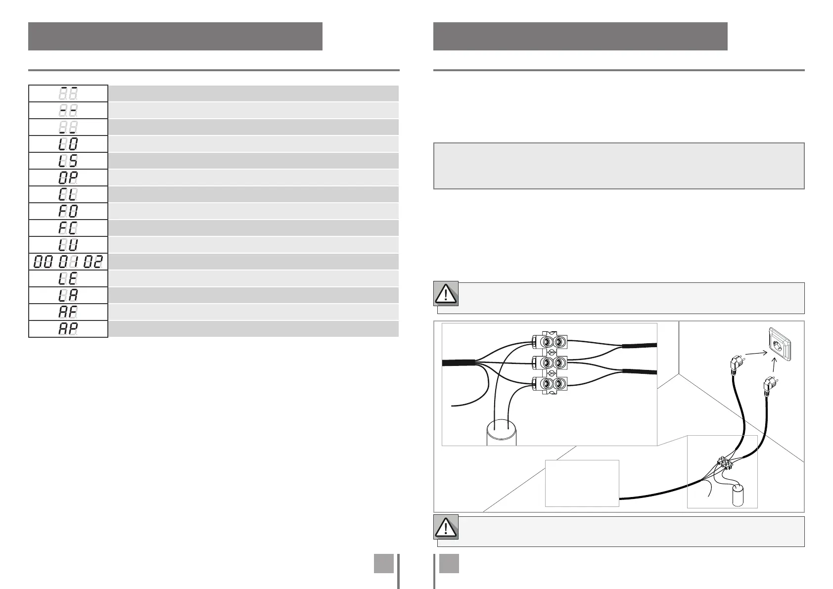
To detect if the problem is in the control board or in the motor, sometimes it's necessary to
conduct tests with a direct connection to a V/V power supply.
For this, it's necessary to interpose a capacitor on the connection so that the motor can work
(check the capacitor type to be used in the product's manual). In the below diagram is shown
how this connection must be made and how to merge the different component wires.
01 • Connect the power wires to the terminal as shown below.
02 • Connect the automation wires to the terminal, interleaving a capacitor into the opening
and closing wires.
03 • After these connections are complete, connect to a 230V/110V power socket, depending
on the motor/control board being tested.
NOTES:
• To perform the tests you don't need to remove the automatism from it's place, because this way you
can understand if the automatism, directly connected to the power, can function correctly.
• A new capacitor should be used during this test to ensure that the problem is not in the capacitor.
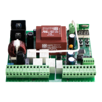
. COMPONENTS TEST
V/V MOTOR
IN STOP POSITION, FULLY OPENED
IN STOP POSITION, MIDDLE POSITION
IN STOP POSITION, FULLY CLOSED
TOTAL OPENING BUTTON PRESSED
PEDESTRIAN OPENING BUTTON PRESSED
CONTROL BOARD PERFOMS OPENING COURSE
CONTROL BOARD PERFOMS CLOSING COURSE
END OF OPENING COURSE TIME
END OF CLOSING COURSE TIME
ALL REMOTE CONTROLS DELETED
REMOTE CONTROL ADDED IN THE INDICATED POSITION
OBSTRUCTED PHOTOCELL
OBSTRUCTED PHOTOCELL
IN PAUSE TIME
IN PEDESTRIAN PAUSE TIME
DISPLAY INDICATIONS
. DISPLAY
All tests must be performed by qualified personnel due to serious danger associated with the
misuse of electrical systems.
The use of capacitors depends on the type of motor to be installed. Check in the
motor manual, if it is necessary to place the capacitors, as shown in the diagram.
Motor
Phase
Close
Power Supply
Power Supply
AUTOMATION
COM
Open
Phase
COM
COM
Ground
Wire
Capacitor
F (V) / F (V)
 Loading...