5
L N
~ ~
~ ~
~ ~
TX
+
1 2
-
RX
+
-
COM
NC/
NO
1 2 3 4
TX
+
1 2
-
RX
+
-
COM
NC/
NO
1 2 3 4
V+
LO LS LE LA
MENU UP
CMD DW
24 25
22 2320 21
18 19
16 17
14 15
1211 13
2928
2726
30
98 1021 3
L+V+
LO LELS LA
6 74 5
N L COMAB
LAMP
FE COMAB FE
B GRY V+
EN
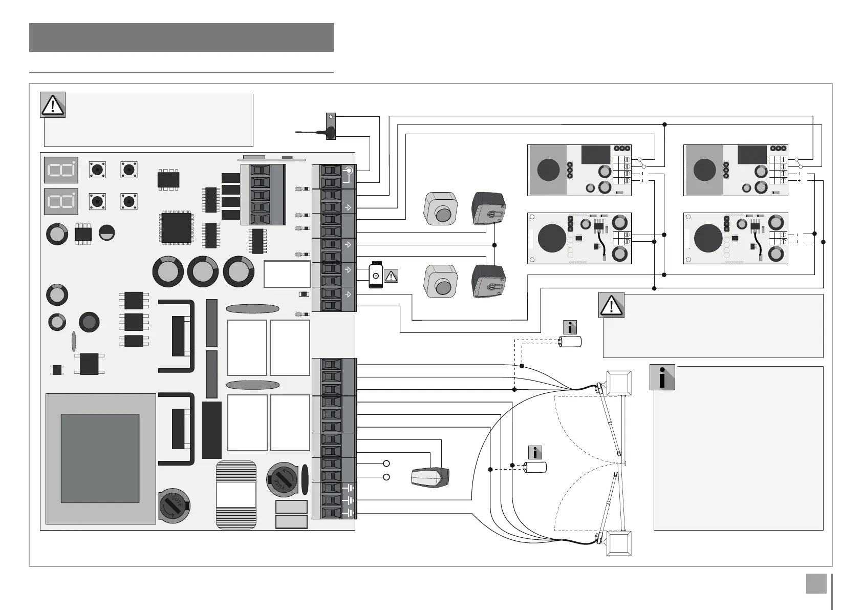
. INSTALLATION
INSTALLATION MAP
Exterior Photocells* Interior Photocells*
Electric Lock
Pushbutton or
Key Selector
Pushbutton or
Key Selector
or
or
Flashing light
Fuse
63mA
Fuse 8A
Antenna
Motor 1
Motor 2
• The use of capacitors
depends on the type of motor
to be installed. Check in the motor
manual, if it is necessary to place the
capacitors, as shown in the diagram.
• Motor opens first than Motor .
• Motor closes first than Motor .
NOTE • When programming, the first
operation of each leaf must be the
opening operation. In case of closing
operation, change the brown and
black wires of this motor.
•
The photocell safety circuits are supplied by
default deactivated (no shunt required).
To activate them go to menu P and P.
• If you do not press any button for sec. the
control board will return to standby.
If you activate the EL option in the E5 menu,
the electric lock must not be powered by the
control board. To do this, use an external power
supply to power the electric lock.