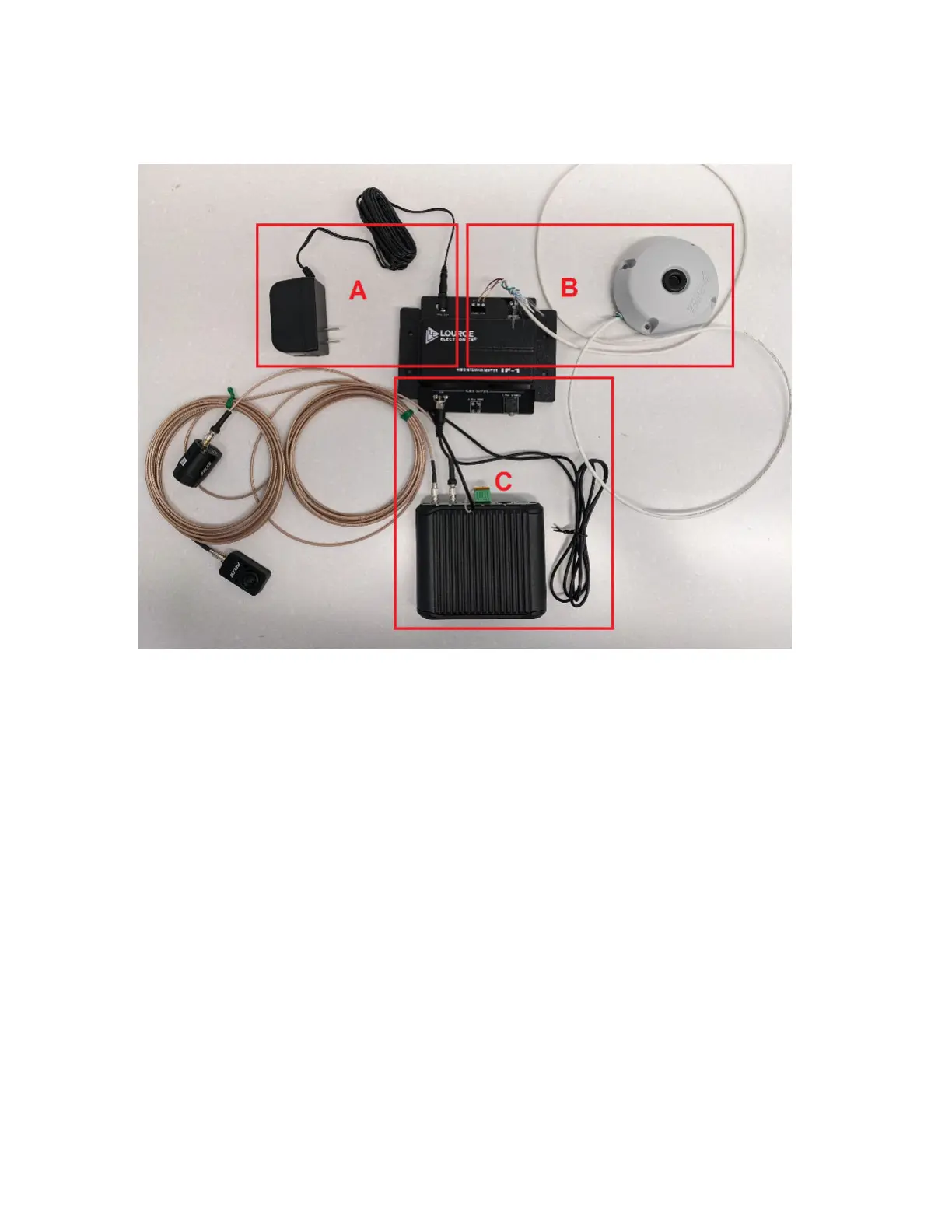
To set up the audio monitoring system, perform the following steps:
Figure 7: Audio Monitoring System Setup – Reference
1. Connect the power adaptor to the +12 Vdc connector on the Audio Interface Adaptor (see A).
2. Connect the Shielded Cable to the MIC INPUT connector on the Audio Interface Adaptor on one side,
and the Microphone on the other side (see B).
● The Shielded Cable must be stripped.
● Connect A to A, B to B, and C to C.
C will be the bare wire.
● For detailed instructions, see Audio Monitoring System Installation and Operating Instructions.
3. Connect the RCA Cable to RCA AUDIO OUTPUT connector on the Audio Interface Adaptor on one side,
and the camera's I/O connectors on the other side (see C).
● One end of the RCA cable must be stripped to connect to the camera's I/O connector.
● The ground wire connects to the ground I/O connector, and the other wire connects to the Audio In
I/O connector.
● For more details on connecting to the camera's I/O, see the camera's Installation Manual:
○ Pelco Sarix Pro 4 Dome Camera: see Connecting to Power and External Devices.
○ Pelco Sarix Modular System: see Connecting to External Audio and I/O Devices.
MN010550A01-A
Chapter 3: Interview Room Hardware Component Details
14