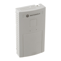
Motorola AP-5131 Access Point Quick Setup Guide
NOTES
• Power Injector
o The power injector can cabled be up to 300 ft from the AP device for final
installation.
o Do Not block or cover airflow to the Power Injector
o Keep the Power Injector away from excessive heat, humidity, vibration and
dust.
o The power injector is not a repeater, and does not amplify the Ethernet
signal. Ensure the Power Injector is placed as close as possible to the
network data port.
• Scale Configuration
o Refer to the following documents for wireless configuration information.
These items can be found on the Rice Lake Weighing Systems Retail
Solutions distributor site at www.ricelake.com/retail
or the Rice Lake Retail
System Support Tool CD (p/n 77369).
o AC-4000: Symbol CB3000 Client Bridge Quick Setup (p/n 93207)
o BC-4000: BC-4000 CB3000 Quick Setup (p/n 101875)
o SR-2000a: SR-2000a Quick Setup Instructions
• Channel Selection
o The AP-5131 default setting is Automatic Selection. This enables the AP-
5131 to auto-select the channel of operation. For example, if three AP-5131
Access Points are operating, each AP-5131 would be set to a non-
overlapping channel (1, 6 and 11).
o If non-Motorola (Symbol) Access Points are also in use the channel can be
manually set to avoid interference. Channel selection is made under Network
Configuration, Radio Configuration, Radio 1. See figure 13.
Figure 13. AP-5131 Manual Channel Selection
Rev 1, February 2009 (10) Motorola_AP5131_Quick_Setup

 Loading...