6881086C22-B 85
Appendix A - Cross Patch Configuration
General Description
The Cross Patch provides interoperability between two systems on different bands, analog or digital or trunking. An
interface cable can be built to allow the interconnection of two ASTRO Spectra/Spectra Plus Consolette stations to
form a repeater system. The information received by Consolette 1 will be retransmitted or repeated by Consolette 2.
Similarly, information received by Consolette 2 will be retransmitted on Consolette 1. The system is a first come, first
served system in that one station does not have priority over the other. Moreover, the Consolettes must be located
in different frequency bands to prevent RF interference from occurring from one Consolette to another.
Detailed Description
To enable Cross Patch operation between two Consolettes, build the cable shown in the Cross Patch Cable diagram
below and connect each dB-25 connector to Accessory Connector 2 of the two Consolettes. If you wish to have the
option of enabling/disabling Cross Patch operation, you must include an in-line switch (or switches) to open and
close the connection between SPKR_UNMUTE and PTT, along with the connection between RX+(LINE1+)† and
TX_AUD(AUD_TX)†. To disable the Cross Patch, the connection between SPKR_UNMUTE and PTT must be open.
This will prevent the Consolette that is receiving information from keying the Consolette it is connected to. In
addition, the connection between RX+(LINE1+)† and TX_AUD(AUD_TX)† must also be switched open to prevent
received audio from one Consolette unintentionally mixing into the connected Consolette's microphone audio.
The PTT for Consolette 2 is derived from the SPKR_UMUTE signal of Consolette 1 which is active when
Consolette 1 is receiving information. RX audio from Consolette 1 is routed to the TX Audio of Consolette 2.
Adjusting the potentiometer (R111 on AIB, R545 on TRC) on the RX Audio path of Consolette 1 will enable the user
to match the transmitter audio input sensitivity of Consolette 2. The behavior of the audio path from Consolette 2 to
Consolette 1 is identical to the Consolette 1 to Consolette 2 path just described.
NOTE: In this configuration, the SPKR_UNMUTE jumper (J15 on AIB, P102 on TRC) should be placed
for active low operation. (See Table 2 on page 9 for AIB and Table 6 on page 11 for TRC jumper
location.)
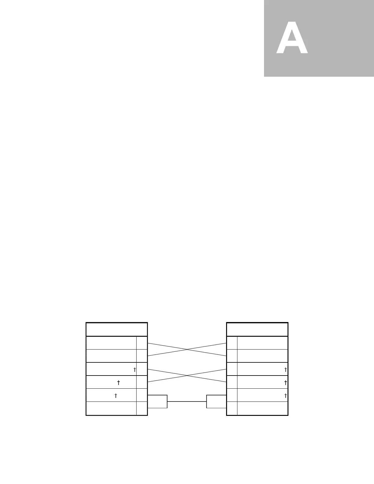
Cross Patch Cable
Notes: * Denotes active low signal
† Denotes TRC signal name
10
25
17
1
16
12
10
25
17
1
16
12
PTT*
SPKR_UNMUTE
TX_AUD(AUD_TX)
RX+(LINE+)
RX-(LINE-)
DIG_GND
Consolette 1
PTT*
SPKR_UNMUTE
TX_AUD(AUD_TX)
RX+(LINE+)
RX-(LINE-)
DIG_GND
Consolette 2

 Loading...


