Installation: DIP Switch and Jumper Settings
6881086C22-B 11
BOLD indicates factory default setting
BOLD indicates factory default setting
BOLD indicates factory default setting
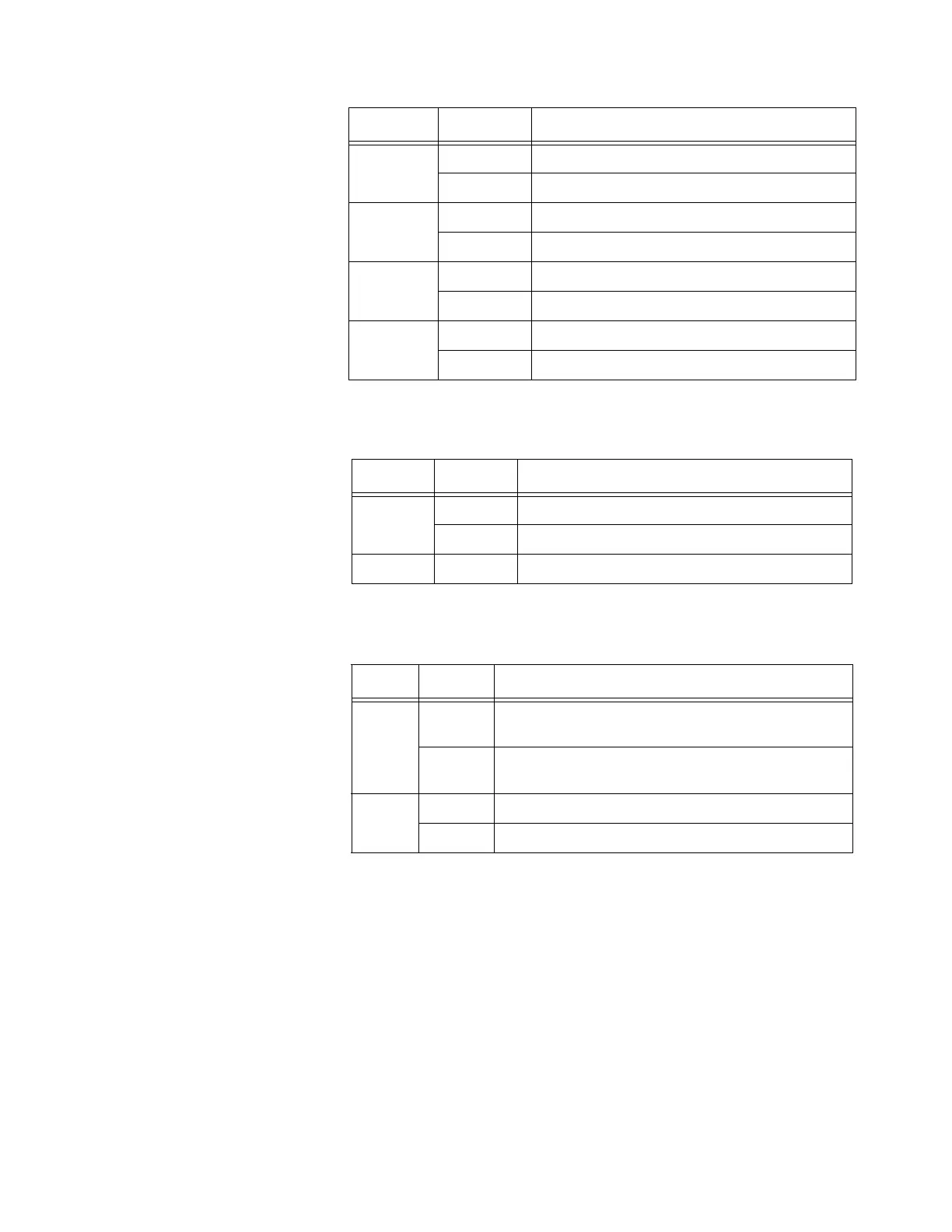
S101-5
ON 900Ω impedance
OFF 600Ω impedance
S101-6
ON Local desk microphone not present
OFF Local desk microphone present
S101-7
ON Two-wire operation
OFF Four-wire operation
S101-8
ON Four-wire operation
OFF Two-wire operation
Table 5. Tone Remote Control Board Jumper Settings
Jumper State Description
JU100
IN Crystal frequency shift circuit enabled
OUT Crystal frequency shift circuit disabled
JU101 IN Always placed for ASTRO
Table 6. Tone Remote Control Board Plug Settings
Plug Jumper Description
P101
A-B
Transmitted and received audio is routed to
TAPE_OUT (Accessory Connector 3, pin 11)
B-C
Only received audio is routed to TAPE_OUT
(Accessory Connector 3, pin 11)
P102
A-B SPKR_UNMUTE active high
B-C SPKR_UNMUTE active low
Table 4. Tone Remote Control Board DIP Switch Settings (S101) (cont’d)
Switch State Description

 Loading...


