Home
Motorola
Radio
ASTRO W3
Page 60
Motorola ASTRO W3 - Page 60
126 pages
Manual
Save Page as PDF
To Next Page
To Next Page
To Previous Page
To Previous Page
Loading...
6-4
Radio Connectors:
E
xtender Cable (
P501)
Septem
ber 26, 20
03
6881096C
77-O
6.3
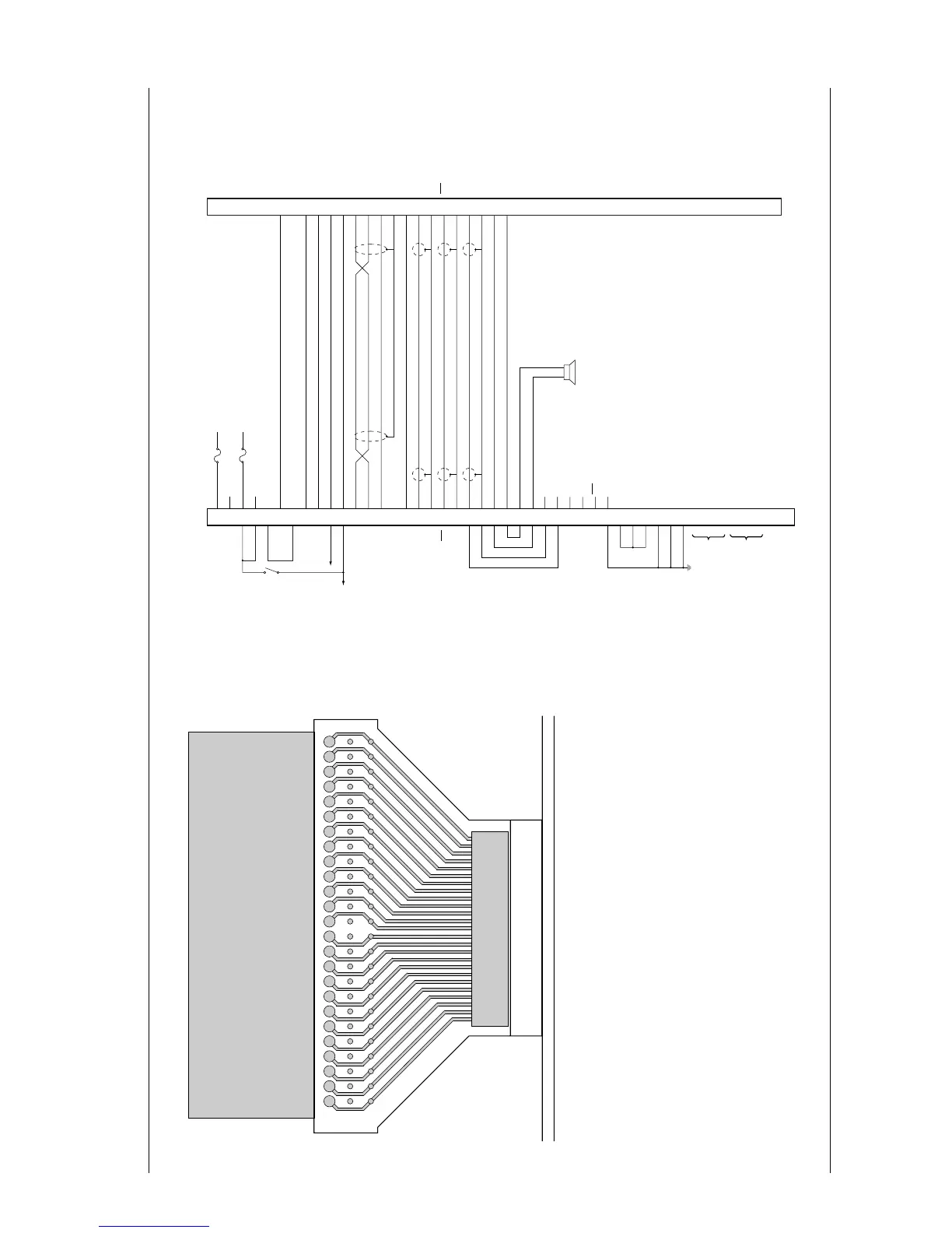
Extender Cable (P501)
Figure 6-10. P
501 Extender Ca
ble
6.4
Control-Head Cabling Diagram
Figure 6-1
1. Control-Head C
abling Diagram
15
17
1
9
1
3
1
1
97531
21
23
25
27
29
31
33
35
37
39
41
43
45
47
49
16
18
20
14
12
10
8
642
22
24
26
28
30
32
34
36
38
40
42
44
46
48
50
P501
EXTENDER
CABLE
(3080370E06)
(FACING TOWARD
CONTROL HEAD)
J501
COMMAND BOARD
P1001
SPARE 2
EMERGENCY
SPARE 1
DIG GND
SWB+
BUS +
BUS -
BUSY
BUS SHIELD
RESET
DET AUDIO
ANA GND
PTT
MIC HI
MIC LO
SPKR HI
SPKR LO
A+
RSSI
RX AUDIO
RED
VIO
BRN
BLU
YEL
WHT
BLK
BLK/RED
BARE
BLK/ORG
BLK/BRN
SHIELD
BLK/GRN
SHIELD
BLK/YEL
SHIELD
ORG
GRN
CONTROL HEAD
ORG
GRN
NC
NC
MIC LO
MIC HI
SWB+
HUB
PTT
PTT/HUB REF
SWB+
SWB+
SWB+
DIG GND
DIG GND
DIG GND
(DATA IN)
(STROBE)
(CLOCK)
(DATA OUT)
BUS +
BUS -
BUSY
RESET
DET AUDIO
ANA GND
PTT
IGN+
IGN-
BATT+
BATT+
BATT-
SPARE 2
BATT-
EMERGENCY
SPARE 1
BLK/GRN
BLK/ORG
DIG GRD
SWB+
P5
RADIO
15
32
47
30
31
29
14
27
28
49
48
17
50
33
26
45
16
46
12
13
44
11
10
43
7
8
41
40
24
23
18
19
3
20
21
36
4
3
37
2
1
34
38
5
SPEAKER
17
13
16
18
22
5
14
23
21
19
9
0
1
12
11
25
24
20
15
7
1
2
3
1
2
3
VIP IN
VIP OUT
59
61
Table of Contents
Main Page
Foreword
4
Manual Revisions
4
Computer Software Copyrights
4
Document Copyrights
4
Disclaimer
4
Trademarks
4
Table of Contents
5
Commercial Warranty
13
Limited Warranty
13
Motorola Communication Products
13
What this Warranty Covers and for How Long
13
General Provisions
13
State Law Rights
14
How to Get Warranty Service
14
What this Warranty Does Not Cover
14
Patent and Software Provisions
15
Governing Law
15
Chapter 1 Introduction
17
Notations Used in this Manual
17
Control Head Features
18
Control Heads
18
W3 Control Head
18
Table 1-1. ASTRO Digital Spectra/Spectra Plus Basic Features
18
Figure 1-1. Typical W3 Hand-Held Control Head
19
W3 Controls
19
W4, W5, W7, and W9 Control Heads
20
Figure 1-2. Typical W4 Rotary Control Head
20
Figure 1-3. Typical W5 Pushbutton Control Head
20
Figure 1-4. Typical W7 Pushbutton Control Head
21
Figure 1-5. Typical W9 Pushbutton Control Head
21
W4, W5, W7, and W9 Controls
22
Table 1-2. 12-Button Keypad (W7 and W9)
23
Chapter 2 Basic Maintenance
25
Inspection
25
Cleaning
25
Cleaning External Plastic Surfaces
25
Cleaning Internal Circuit Boards and Components
25
Handling Precautions
26
Chapter 3 Theory of Operation
27
W3 Control Head
27
SB9600 Serial Bus Interface
27
Display Circuit
27
Keypad Side Keys and Top Keys
28
Microphone Preamplifier and PTT
28
On-/Off-Hook Control
29
Backlight Circuit
29
Power Supply
29
Status Leds
29
Jumper Selection
29
Table 3-1. W3 Jumper Selection
29
Power On/Off
30
Miscellaneous Functions
30
W4, W5, and W7 Control Heads
30
Power Switch/Ignition
30
Figure 3-1. Astro Spectra Control Head Block Diagram
30
Table 3-2. Types of Operations
30
Voltage Regulator
31
Microcomputer
31
Interface Circuitry
31
Reset
32
Bus Busy
32
Serial Bus Data
32
Table 3-3. Serial Data Bus Logic
32
Push-To-Talk (PTT)
33
Hang-Up Button (HUB)
33
Ignition Sense Circuitry
33
Keypad Scan
33
Vacuum Fluorescent (VF) Voltage Converter Circuitry
33
Table 3-4. PTT Logic States
33
Table 3-5. HUB Logic States
33
Vacuum Fluorescent Display Driver IC
34
Vacuum Fluorescent Display
34
Backlight Leds
34
W9 Control Head
34
Display
34
W9 Controls and Indicators
35
Control Board
35
Microprocessor
35
Watchdog Timer
35
Bus Transceiver
36
Vacuum Fluorescent Voltage Converter
36
Vehicle Interface Ports
36
Power Supply
36
Ignition Sense Circuits
36
EEPROM Write-Protect Circuit
37
Display Board
37
VF Display
37
VF Display Driver
37
Status Leds
37
Backlight Leds
37
Default Jumper Settings
37
Table 3-6. Standard Jumper Configurations
37
Vehicle Interface Port (VIP)
38
W4, W5, and W7 Control Heads
38
VIP Output Connections
38
Dash-Mount Installations
38
Remote-Mount Installations
39
VIP Input Connections (Remote-Mount Only)
39
Figure 3-2. Cabling Interconnect Diagram for Dash Mount
39
Figure 3-3. Cabling Interconnect Diagram for Remote Mount
39
W9 Control Heads
40
VIP Output Connections
40
VIP Input Connections
40
Chapter 4 Test Equipment and Service Aids
41
Recommended Test Equipment and Service Aids
41
Table 4-1. Recommended Motorola Test Equipment and Service Aids
41
Chapter 8 Schematics, Overlays, and Parts Lists
43
Troubleshooting Waveforms
44
ASTRO Digital Spectra Waveforms
44
Replacing the Vacuum Fluorescent Display (W4, W5, and W7 Control Heads)
47
Removing the Display
47
Installing the Display
47
Replacing the Remote Back-Housing Interface Board
47
W4, W5, and W7 Control Heads
47
Replacing the Remote Interconnect Board
48
Low-/MID-Power Radios
48
High-Power Radios
48
Replacing the Control-Head Board
49
W3 Control Heads
49
W4, W5, and W7 Control Heads
50
Figure 5-2. Model W4 Rotary Control Head Assembly Screw and Snap Sequence
50
Figure 5-3. Models W5 and W7 Pushbutton Control Head Assembly Screw Sequence
50
Chapter 5 Troubleshooting
43
Required Tools and Supplies
43
Table 5-1. Required Tools and Supplies
43
Chapter 7 Exploded Views and Parts Lists
50
W9 Control Heads
52
Figure 5-4. W9 Control Head Control Board and Display Board
52
Table 7-5. W9 Pushbutton Control Head Parts List
52
Final Reassembly-W3 Control Head
53
Table 7-2. W3 Hand-Held Control Head Exploded View Parts List
53
Troubleshooting Charts
54
A.1 Basic Ordering Information
121
A.2 Motorola Online
121
A.3 Mail Orders
121
A.4 Telephone Orders
122
A.5 Fax Orders
122
A.6 Parts Identification
122
A.7 Product Customer Service
122
Figure 5-1. Replacing the Vacuum Fluorescent Display
123
Index
123
Table 3-7. VIP Output Connections
124
Table 3-8. VIP Input Connections
124
Small Pushbutton Parts
124
Large Pushbutton Parts
124
Related product manuals
Motorola ASTRO 25
36 pages
Motorola ASTRO Series
25 pages
Motorola ASTRO APX O9
95 pages
Motorola ASTRO SPECTRA
114 pages
Motorola Astro XTL 5000
158 pages
Motorola Astro XTL 1500
452 pages
Motorola ASTRO XTL 2500
161 pages
Motorola ASTRO 25 GTR 8000
309 pages
Motorola ASTRO Digital Spectra
442 pages
Motorola ASTRO Digital XTL 5000
38 pages
ASTRO Digital Spectra Plus
442 pages
Astro APX Mobile 05 control head
138 pages
 Loading...


