3-2 RF Test Mode
Supply voltage can be connected from the battery eliminator. The equipment required for alignment
procedures is connected as shown in the Radio Performance Checks Setup diagram (Figure 3-1).
Initial equipment control settings should be as indicated in the following table and should hold for all
alignment procedures, except as noted in Table 3-1.
3.3 RF Test Mode
When the CP150/CP200 radio is operating in its normal environment, the radio's microcomputer
controls the RF channel selection, transmitter key-up, and receiver muting, according to the customer
codeplug configuration. However, when the unit is on the bench for testing, alignment, or repair, it
must be removed from its normal environment using a special routine, called RF TEST MODE. The
RF Test Mode is a special routine that has been incorporated in the radio. This mode allows bench
testing of the radio at various test frequencies across the entire band, at both high and low transmit
power (if applicable), at various channel spacings, and with different coded or carrier squelch types.
Any customer specific programming in the radio will not be changed or affected by use of the RF Test
Mode.
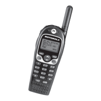
Figure 3-2 Side Button Locations
Table 3-1 Initial Equipment Control Settings
Service Monitor Test Set Power Supply
Monitor Mode: Power Monitor Spkr set: A Voltage: 7.5Vdc
RF Attenuation: -70 Spkr/load:
Speaker
DC on/standby:
Standby
AM, CW, FM: FM PTT: OFF Volt Range: 10V
Oscilloscope Source: Mod
Oscilloscope Horiz: 10mSec/Div
Oscilloscope Vert: 2.5kHz/Div
Oscilloscope Trig: Auto
Monitor Image: Hi
Monitor BW: Nar
Monitor Squelch: mid CW
Monitor Vol: 1/4 CW
Current: 2.5A
Side Button 1
Side Button 2

 Loading...