Installation
Connecting to a Digital Junction Box
MC3000 Digital Deskset Operator and Installation Manual 2-9
(6880309L15-A)
Connecting to a Digital Junction Box
The deskset is connected via an 8-wire CAT-5 cable (4 wires for audio and 4 wires for
data) to the Digital Junction Box which is connected to the radio. (See Figure 2-9.)
Desksets are shipped with the line terminations active. When parallel desksets are con-
nected, only the farthest deskset should be terminated.
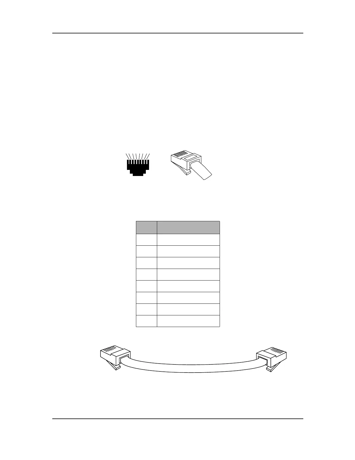
Connect the cable from the Digital Junction Box to the 8-pin RJ45 connector labeled
“Audio/Data” on the back left hand side of the bottom housing. The pins are numbered in
ascending order from top to bottom and left to right.
Figure 2-8: RJ45 Connectors
Table 2-4: Audio and Data to Radio RJ45 Pinout
Pin # Function
1 Ground
2Busy
3 Receive +
4 Transmit +
5 Transmit -
6 Receive -
7Data -
8Data +
Figure 2-9: MC3000 Deskset to Digital Junction Box Cable
8
7
65
4
3
21
1
2
3
4
5
6
7
8
BACK
VIEW
FRONT
VIEW
RJ45 8-WIRE
1
2
3
4
5
6
7
8
To MC3000
Deskset
To Digital Junction Box
Console/Deskset Port
1
2
3
4
5
6
7
8
 Loading...