Installation
Connecting Power Supply
2-12 MC3000 Digital Deskset Operator and Installation Manual
(6880309L15-A)
Connecting Power Supply
All power connections are made to the 9-pin mini-DIN connector PWR1 labeled “12V DC”
on the back right-hand side of the bottom housing. The power source must supply
between 10.5 and 16 volts dc and 0.5 amperes per deskset.
Connecting an External Deskset Microphone or Footswitch
Connecting an external deskmic or footswitch will disconnect the deskset’s internal micro-
phone.
Connect the desk microphone to two connectors J1and J3 at the back of the deskset. The
footswitch is connected to the 3-pin connector J1 labeled “Footswitch”. The headset or
deskmic is connected to the 8-pin RJ45 connector J3 labeled “Deskmic Headset” at the
back of the deskset. The pins are numbered in ascending order from top to bottom and left
to right.
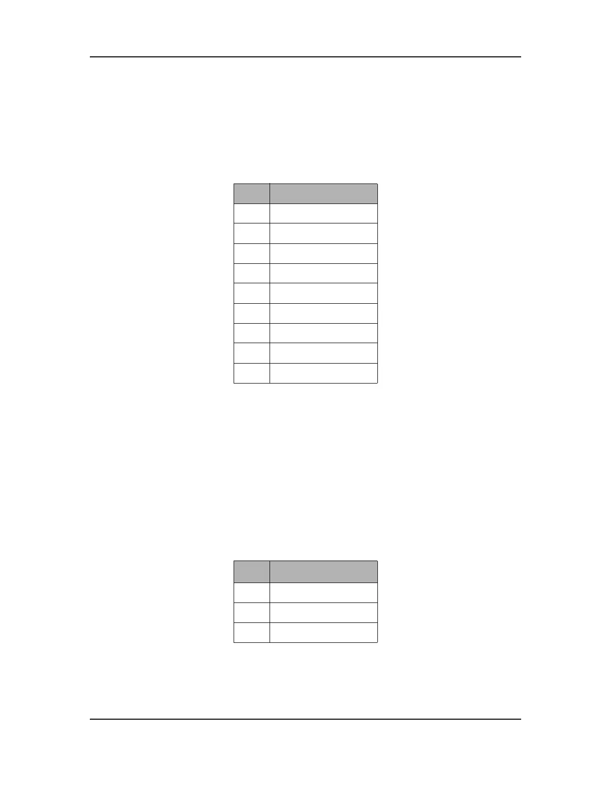
Table 2-6: PWR 1 Power Supply Mini-DIN Pinout
Pin # Function
1Ground
2 Not used
3 In_+ 12 V
4Ground
5 In_+ 12 V
6 In_+ 12 V
7 Shield 1
8 Shield 1
9 Shield 1
Table 2-7: J1 Footswitch 3-pin Connector Pinout
Pin # Function
1PTT
2Ground
3 Monitor (not used)
 Loading...