MAINTENANCE 6 - 13
3. Press the dismantling tool until the snap connectors on the side of the back housing release
from the Enhanced Control Head.
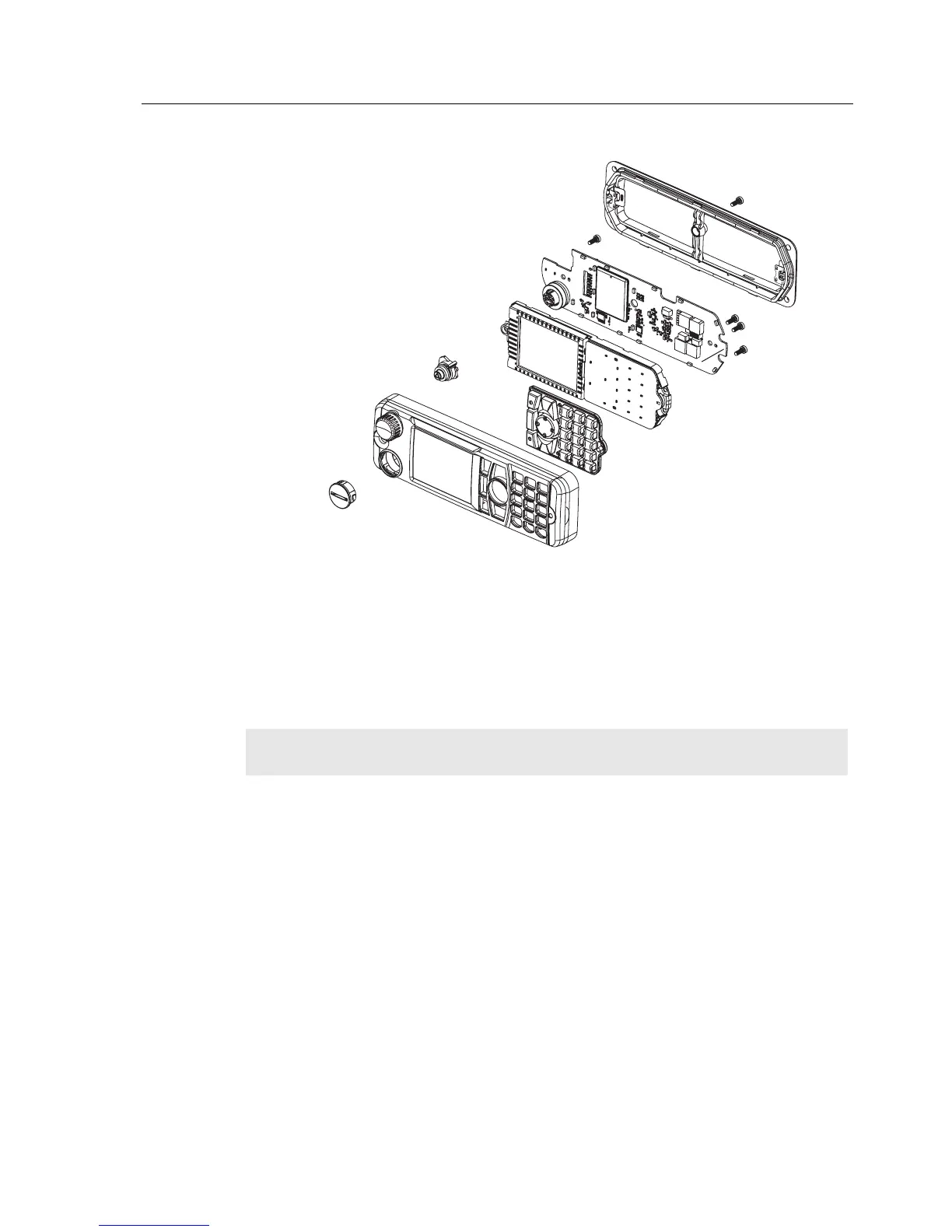
Figure 6-8 Enhanced Control Head Board Removal
4. Remove the board from the Enhanced Control Head front housing by unscrewing the screws
using a T10 TORX™ and disassemble the encoder switch flex from the socket on the board.
5. Remove the board from the Enhanced Control Head housing by stretching the Enhanced
Control Head housing and pulling up the board.
6. Remove the keypad by gently pressing the keypad out from the Enhanced Control Head front
housing.
Enhanced Control Head – Reassembly
1. Fit the rubber keypad onto the Enhanced Control Head housing and ensure that the keypad is
correctly aligned and pressed onto the groove on the front housing.
2. Assemble the board to the Enhanced Control Head front housing.
3. Assemble the encoder switch flex to the socket on the board.
4. Screw the two 8mm self tapping screws and one 14mm self tapping screw.
NOTE
Care should be taken not to touch or contaminate the conductive pads on the under
side of the keypad or the conductive contacts on the printed circuit board.
ZWG0130215-O
 Loading...