Hardware Setup
19
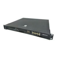
4.7 Verifying the Installation
View the LEDs on the front panel of the RFS6010 RF Switch to ensure the device is functioning
properly. The normal LED pattern follows this path:
• During the Power On Self Test (POST), the System 1 and System 2 LEDs both blink green.
• If the POST test fails, the System 1 LED will blink amber. If the POST test succeeds, the System
1 LED will be lit solid green.
• As the software is initialized, the System 2 LED will blink green.
• After the software has finished initializing, the System 1 LED will be lit solid green and the
bottom System 2 LED will be off. The RFS6000 Series RF Switch is ready to be configured, as
described in the Motorola RF Switch System Reference.
Other LED codes indicate the presence (or absence) of different standby states, or errors. A guide to
the RFS6000 Series RF Switch LEDs codes is provided in LED Codes.
 Loading...