iii
LIST OF FIGURES
LIST OF TABLES
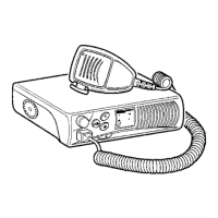
Figure 1 Typical Spectra Control Heads .............................................................................................................7
Figure 2 Functional Block Diagram for Pushbutton Control Head ....................................................................11
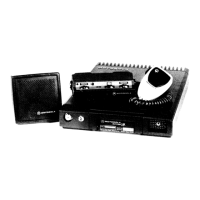
Figure 3 Typical Systems 9000 Control Unit.....................................................................................................12
Figure 4 Disassembly of the Control Unit..........................................................................................................15
Figure 5 Systems 9000 Control and Programming Control Controls................................................................18
Figure 6 Top-Level Menu..................................................................................................................................18
Figure 7 Lower-Level Menu Structure...............................................................................................................19
Figure 8 Zone Parameters Menu ......................................................................................................................19
Figure 9 Mode Parameters Menu .....................................................................................................................20
Figure 10 Changing Mode Names ......................................................................................................................20
Figure 11 Editing Scan Lists ...............................................................................................................................21
Figure 12 Service Alignment Diagram ................................................................................................................28
Figure 13 Transmitter Troubleshooting Preferred Test Setup.............................................................................36
Figure 14 Control Head Assembly Screw Sequence..........................................................................................42
Figure 15 Rotary Control Head Assembly Screw and Snap Sequence..............................................................42
Figure 16 PA Board Screw Fastening Sequence................................................................................................43
Figure 17 Installing the Final Device...................................................................................................................44
Figure 18 Removing Memory Board ...................................................................................................................44
Figure 19 Spectra Control Head Self-Test..........................................................................................................50
Figure 20 Spectra 9000 Control Head Self-Test.................................................................................................51
Figure 21 Front Panel Diagnostics; Key Closure Displays..................................................................................52
Figure 21A Front Panel Diagnostics; Rotary Key Closure Displays......................................................................52
Figure 22 Front Panel Diagnostics; Key Closure Displays..................................................................................53
Table 1 Control Head Jumper Table **..............................................................................................................8
Table 2 Serial Data Bus Logic States ................................................................................................................8
Table 3 VCO Frequency ....................................................................................................................................9
Table 4 VCO Power Output (Typical, dBm).......................................................................................................9
Table 5 Mode Jumper Placement....................................................................................................................13
Table 6 EEPROM Jumper Table .....................................................................................................................14
Table 7 VIP Output Connections .....................................................................................................................16
Table 8 VIP Input Connections ........................................................................................................................16
Table 9 Alignment Mode Frequencies .............................................................................................................25
Table 10 Alignment Procedures.........................................................................................................................29
Table 11 Power-Up Self-Check Display.............................................................................................................34
Table 11A Control Unit Troubleshooting Display Codes......................................................................................35
Table 11B SECURENET-Capable Radio Troubleshooting Display Codes..........................................................35
Table 11C Trunking System Troubleshooting Display Codes..............................................................................35
Table 11D Siren/PA Troubleshooting Display Codes...........................................................................................35
Table 12 Transmitting Troubleshooting Chart....................................................................................................37
Table 13 Receiver Troubleshooting Chart .........................................................................................................38
Table 14 Synthesizer Troubleshooting Chart.....................................................................................................40
Table 15 Minimum RF Performance Tests for Board Replacement ..................................................................47
Table 16 Alignment Procedures.........................................................................................................................48
Table 17 Minimum RF Performance Tests for Board Replacement ..................................................................48
Table 18 Signalling Types..................................................................................................................................49
Table 19 Checking Modulation Frequency and Deviation .................................................................................49
 Loading...