Overview 2-15
MB*/* Installation and Operation Manual
Model Description Function
ICS
Ingress Control Switch This option enables remote monitoring, isolation, and
reduction of ingress on the return path by providing
signal attenuation of 6 dB or cutoff of 38 dB typical. The
unit is shipped with a jumper in this location.
SP or DC/*
Output passives These options should be installed in place of the JMP
jumper to activate the third output of the MB*/*.
JXP-RPC
Return Path Correction Board This optional board provides additional flatness
response correction in the return path for systems that
must meet especially stringent return-path flatness
requirements.
MBP-HSG
Bypass housing This housing accommodates the signal bypass jumper,
which prevents transmission loss to subscribers during
maintenance and upgrades.
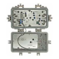
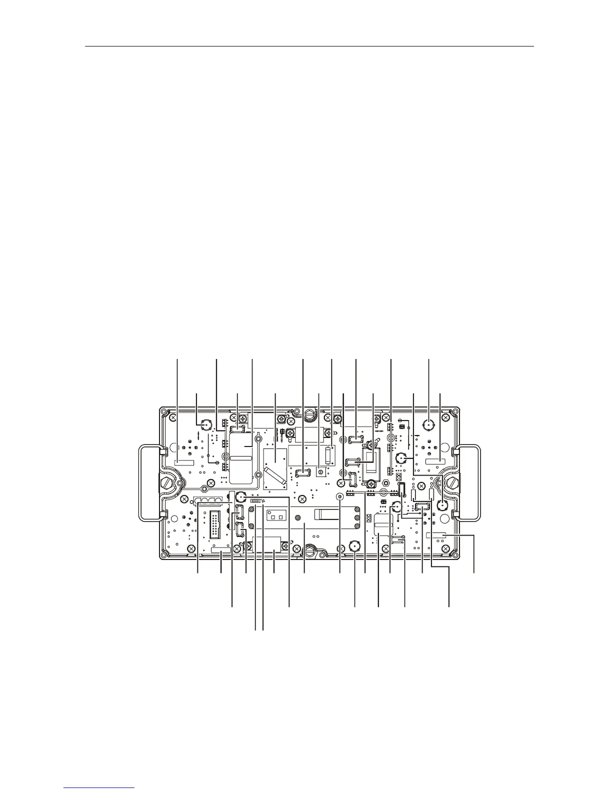
Figure 2-15 illustrates the location of options and accessories in the MB*/*:
Figure 2-15
MB*/* options and accessories
20A
fuse
20A
fuse
Return
equalizer
(SRE-*-*)
20A
fuse
Return
hybrid
Status
monitor
input
Optional
DC/SP
Auto
level
(ADU)
Diplex
filter
Return
pad
(JXP
common)
Optional
ICS
(JXP jumpers
shown)
Return
output
pad
(JXP)
TP
return
output
Optional
(JXP THERM)
TP
forward
output
(3/4)
Return
input
pads
(JXP 2 and
JXP 3/4)
ADU
or TDU
DRIVE UNIT/MAN
Drive
control
select jumper
MDR
Bode
board
20A
fuse
TP
forward
input
TP
return
inputs
Input
pad
(JXP IN)
Mid-stage
pad
(JXP)
Manual
level
(MAN)
ADU
pad
(JXP
ADU)
Output
pad
(JXP 3/4)
Output pad
(JXP 2)
TP forward
output
(Status monitor
output)
Forward
equalizer or
Cable simulator
(SFE-*-* or SCS-*)
Diplex
filter
Diplex
filter
SFE-*-*
DC/*
460246-001
In the event of ADU or TDU board failure, you can select manual control of the Bode board.
Figure 2-15 illustrates the location of the
DRIVE UNIT/MAN jumper on the main circuit board.
 Loading...