Contents iii
MB*/* Installation and Operation Manual
Figures
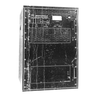
Figure 1-1 MB*/* — closed..............................................................................................................................................................1-2
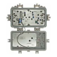
Figure 2-1 MB*/* — open.................................................................................................................................................................2-1
Figure 2-2 MB*/* configurator.........................................................................................................................................................2-2
Figure 2-3 MB-HSG dimensions — top view.................................................................................................................................2-3
Figure 2-4 MB-HSG dimensions — side view ...............................................................................................................................2-3
Figure 2-5 MBP-HSG dimensions ..................................................................................................................................................2-4
Figure 2-6 Housing gaskets............................................................................................................................................................2-5
Figure 2-7 Housing ports................................................................................................................................................................2-6
Figure 2-8 MPPS-II block diagram..................................................................................................................................................2-7
Figure 2-9 MPPS-II power pack ......................................................................................................................................................2-7
Figure 2-10 60/90 volt selector .......................................................................................................................................................2-8
Figure 2-11 Power passing fuse locations....................................................................................................................................2-9
Figure 2-12 MB*/* dual output block diagram.............................................................................................................................2-10
Figure 2-13 MB*/S*single output block diagram ........................................................................................................................2-11
Figure 2-14 LL-MB-F3 status monitor..........................................................................................................................................2-13
Figure 2-15 MB*/* options and accessories................................................................................................................................2-15
Figure 3-1 Equalizer slope versus cable .......................................................................................................................................3-4
Figure 3-2 Frequency versus cable slope.....................................................................................................................................3-6
Figure 3-3 SP splitter.......................................................................................................................................................................3-7
Figure 3-4 DC/* directional coupler................................................................................................................................................3-7
Figure 3-5 Flatness controls...........................................................................................................................................................3-8
Figure 3-6 MDR-*MB/*/II board........................................................................................................................................................3-9
Figure 3-7 Effects of flatness controls on the MDR-8MB/*/II board..........................................................................................3-10
Figure 3-8 Effect of flatness controls on the main board: ........................................................................................................3-11
Figure 3-9 TDU cable selector ......................................................................................................................................................3-14
Figure 3-10 ADU.............................................................................................................................................................................3-15
Figure 4-1 Test equipment connections for bench sweeping ....................................................................................................4-2
Figure 5-1 Center-conductor pin length........................................................................................................................................5-1
Figure 5-2 Torque sequence...........................................................................................................................................................5-2
Tables
Table 2-1 MB*/* options and accessories ...................................................................................................................................2-14
Table 3-1 Starline Forward Equalizers — SFE-*-*.........................................................................................................................3-3
Table 3-2 Starline cable simulators ...............................................................................................................................................3-5
Table 3-3 Gain reserve versus ambient temperature.................................................................................................................3-13
Table 3-4 MB*/* AGC pad levels ...................................................................................................................................................3-16
 Loading...