6 Wiring of the Device
Rev. 03/2019 55
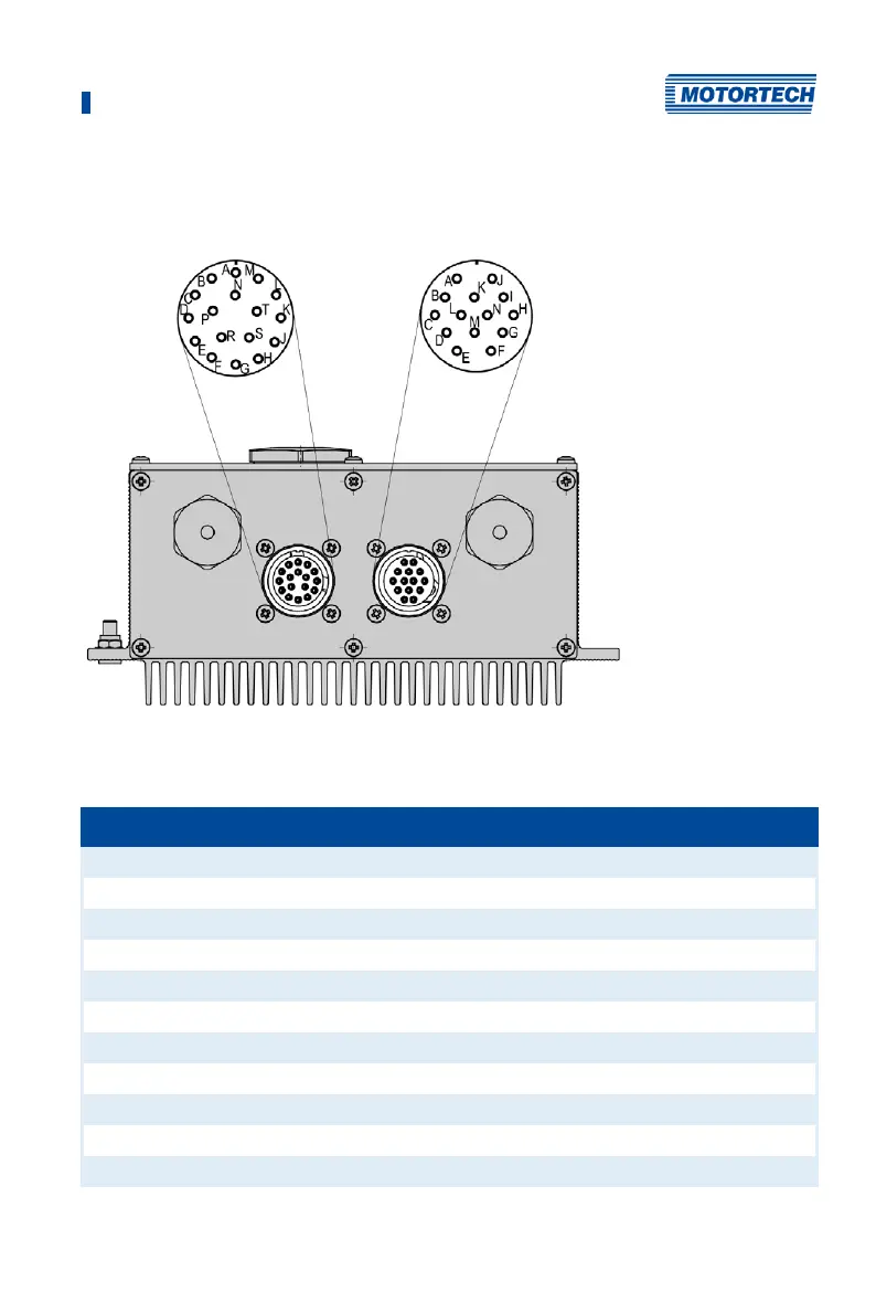
6.2.2 Ignition Coil Wiring 17-Pole and 14-Pole Connector
The table shows the pole assignments for the output connector.
17-pole output connector and 14-pole output connector (MIC5, outside view)
The MIC5-SE has only one 17-pole output connector.
Pole Output (17-pole) Pole Output (14-pole)
A Output A1 A Output B1
B Output A2 B Output B2
C Output A3 C Output B3
D Output A4 D Output B4
E Output A5 E Output B5
F Output A6 F Output B6
G Output A7 G Output B7
H Output A8 H Output B8
J Output A9 I Output B9
K Output A10 J Output B10
N Ground N Ground
 Loading...
