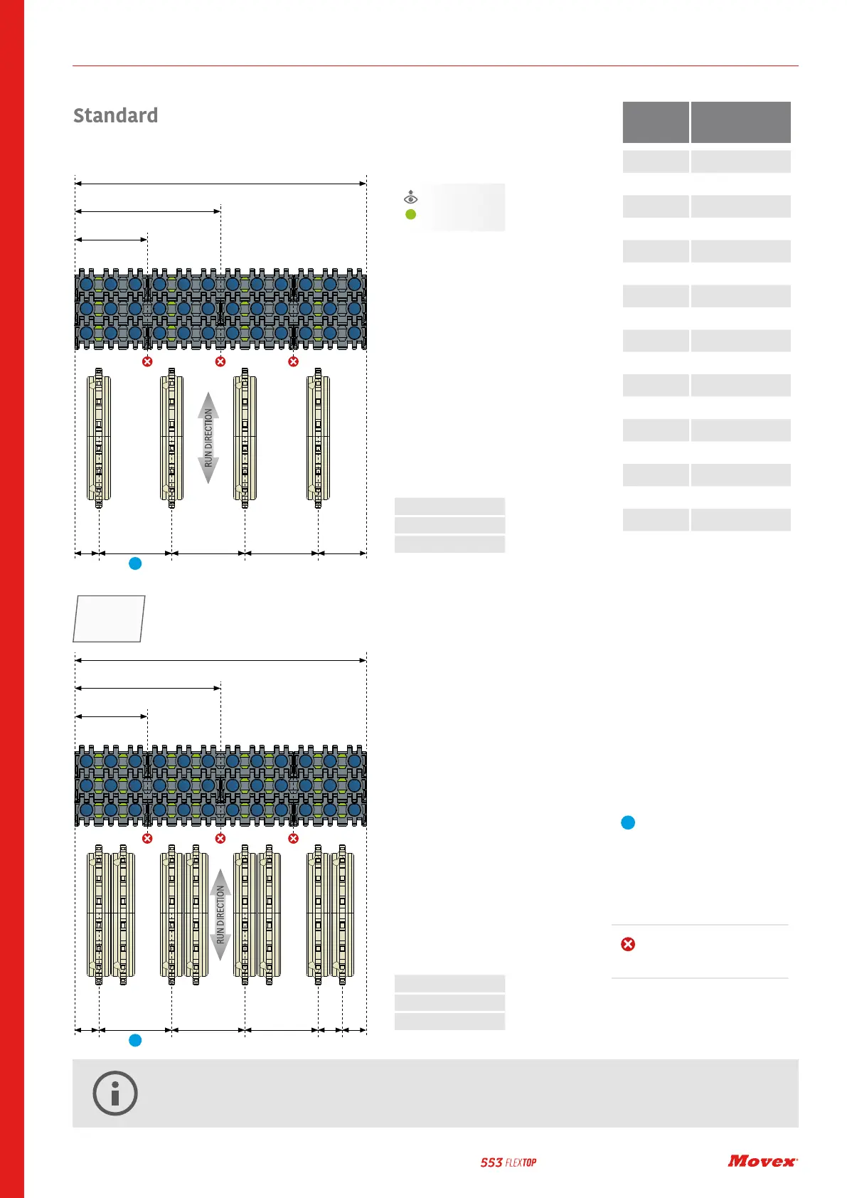
A: 0,99” (25,2 mm)
B: 3” (76,2 mm)
C: 2” (50,6 mm)
A: 0,99” (25,2 mm)
B: 3” (76,2 mm)
C: 1” (25,4 mm)
BOTTOM VIEW
Contact point
M=3”
6”
W (inch)
A ACB B B
M=3”
6”
W (inch)
A CB B B
Belt width
(in/mm)
Recommended n°
of sprockets
3 / 76.2 1
6 / 152.4 2
9 / 228.6 3
12 / 304.5 4
15 / 381.0 5
18 / 457.2 6
21 / 533.4 7
24 / 609.6 8
27 / 685.8 9
30 / 762.0 10
33 / 838.2 11
36 / 914.4 12
39 / 990.6 13
42 / 1066.8 14
45 / 1143.0 15
48 / 1219.2 16
51 / 1295.4 17
54 / 1371.6 18
It’s NOT possible to place
the sprockets in this position.
If more sprockets are required
the Heavy duty position can be
followed.
IMPORTANT
Add sprocket positions
every 76,2 mm according to
76,2 mm width increments of
the belt corresponding with
76,2 mm conveyor track pitch
system.
Sprockets Position
ENGINEERING MANUAL
28
HEAVY DUTY position is ideal in case the load of the application is close to the belt limit or in case there is an high
number of starts/stops during production.
HEAV Y
DUTY