— 10 —
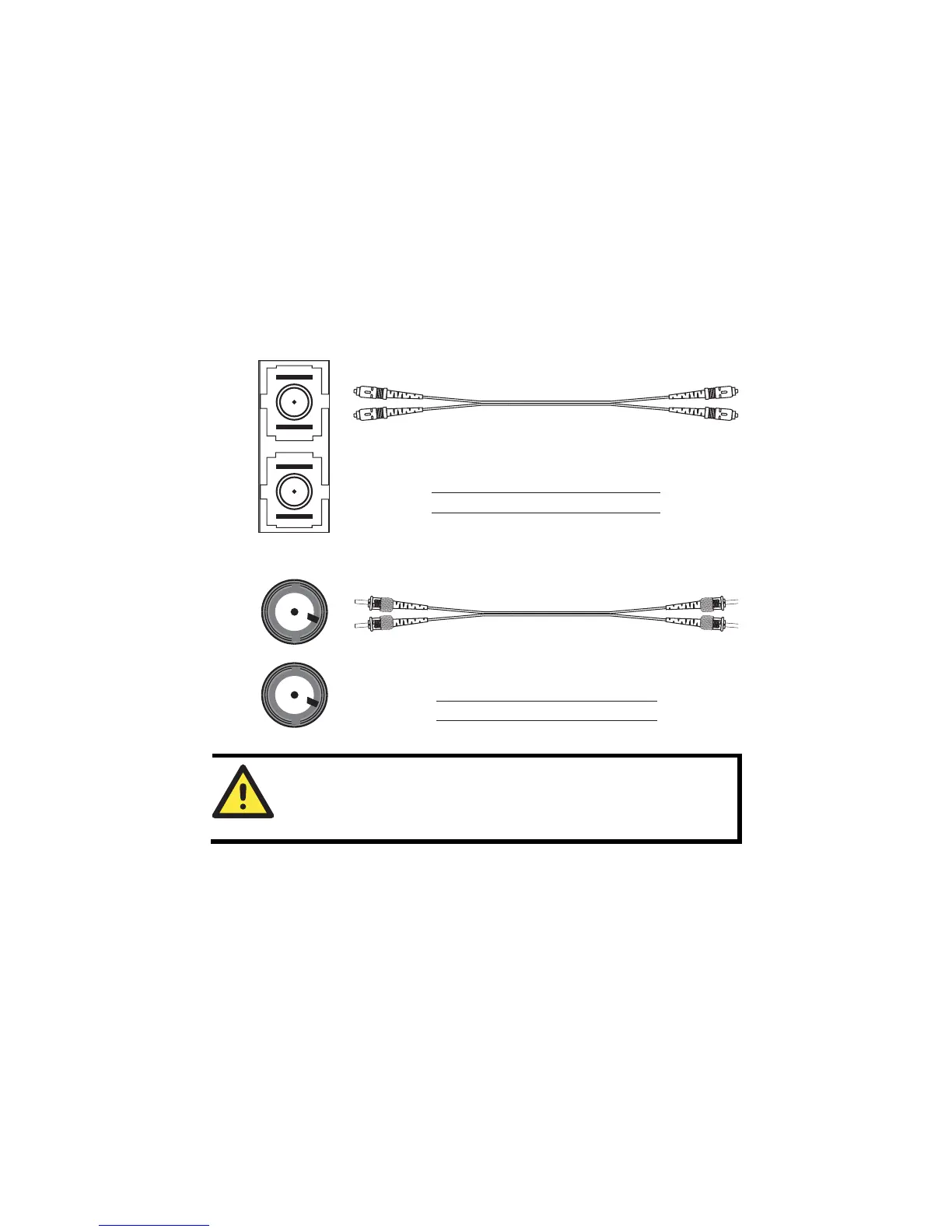
100BaseFX Ethernet Port Connection
The concept behind the SC/ST port and cable is quite straightforward. Suppose
you are connecting devices I and II; contrary to electrical signals, optical
signals do not require a circuit in order to transmit data. Consequently, one of
the optical lines is used to transmit data from device I to device II, and the
other optical line is used transmit data from device II to device I, for
full-duplex transmission.
Remember to connect the Tx (transmit) port of device I to the Rx (receive) port
of device II, and the Rx (receive) port of device I to the Tx (transmit) port of
device II. If you make your own cable, we suggest labeling the two sides of the
same line with the same letter (A-to-A and B-to-B, as shown below, or
A1-to-A2 and B1-to-B2).
SC-Port Pinouts SC-Port to SC-Port Cable Wiring
Tx
Rx
AA
BB
Cable Wiring
A A
B B
ST-Port Pinouts ST-Port to ST-Port Cable Wiring
Tx
Rx
AA
B
Cable Wiring
A A
B B
B
ATTENTION
This is a Class 1 Laser/LED product. To avoid causing serious
damage to your eyes, do not stare directly into the Laser Beam.
Redundant Power Inputs
Both power inputs can be connected simultaneously to live DC power sources.
If one power source fails, the other live source acts as a backup, and
automatically supplies the EDS-408A with power.
Relay Contact
The Moxa EtherDevice switch has one Relay Contact located on the top panel.
For detailed instructions on how to connect the Relay Contact power wires to
the two middle contacts of the 6-contact terminal block connector, see the
Wiring the Relay Contact section. A typical scenario would be to connect the
fault circuit to a warning light located in the control room. The light can be set
up to switch on when a fault is detected.
 Loading...