— 3 —
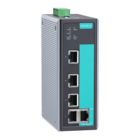
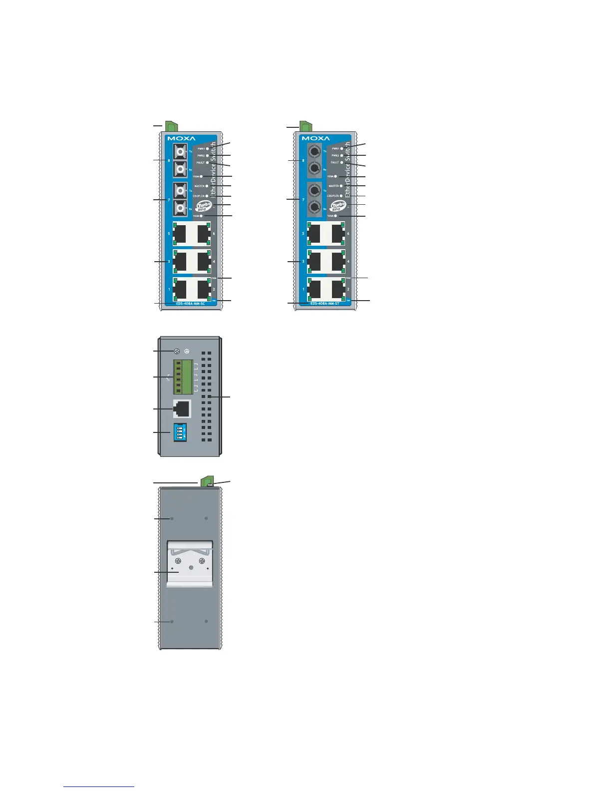
Panel Layout of EDS-408A-MM
(SC & ST-type)
6
7
8
13
2
12
16
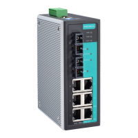
EDS-408A-MM-SC
Front Panel View
15
14
16
9
17
17
10
11
6
7
8
13
2
12
16
EDS-408A-MM-ST
Front Panel View
15
14
16
9
17
17
10
11
V1, V2 INPUTS: 12-45 VDC
V2+
V2-
V1-
V1+
RS-232 CONSOLE
------
MASTER
COUPLER
TURBO
RING
ONOFF
PWR2
RELAY
PWR1
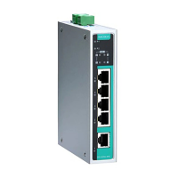
Top Panel View
1
2
3
5
4
1
Rear Panel View
2
19
18
18
4321
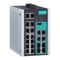
NOTE:
The appearance of EDS-408A-SS-SC is
identical to that of EDS-408A-MM-SC.
1. Grounding screw
2. Terminal block for power input
PWR1/PWR2 and relay output
3. Heat dissipation orifices
4. Console port
5. DIP switches
6. Power input PWR1 LED
7. Power input PWR2 LED
8. Fault LED
9. Master LED
10. Coupler LED
11. Turbo Ring logo
12. TP port’s 100 Mbps LED
13. TP port’s 10 Mbps LED
14. Model Name
15. 10/100BaseT(X) ports
16. 100BaseFX ports
17. FX port’s 100 Mbps LEDs
18. Screw hole for wall mounting kit
19. DIN-Rail kit
 Loading...