- 8 -
Communication Connections
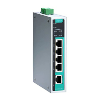
The EDS-P205A-4PoE switches have 4 10/100/1000Base-T(X) PoE
Ethernet ports for connecting PoE devices, and 1 10/100/1000Base-T
port or 1 1000Base-X SFP slot for uplink connection.
10/100/1000Base-T(X) Ethernet Port Connection
10/100/1000Base-T(X) ports located on the EDS’s front panel are used to
connect to Ethernet-enabled devices. Below we show pinouts for both
MDI (NIC-type) ports and MDI-X (HUB/Switch-type) ports, and also show
cable wiring diagrams for straight-through and cross-over Ethernet
cables.
10/100Base T(x) RJ45 Pinouts
1000BaseT RJ45 Pinouts
PoE Ethernet Port Connection
PoE ports located on the EDS switch’s front panel are used to connect to
PoE-enabled devices. The pinout follows the Alternative A, MDI mode” of
802.3af/802.3at standards. Please see the details in the following table.
According to IEEE 802.3af/at standards, the PD shall be
implemented to be insensitive to the polarity of the power supply
and shall be able to operate per MDI mode and MDI
-X mode.
However, some PDs only support MDI mode or
MDI-X mode only.
The following figure shows how to select the correct cable
between the PD and EDS-G205A-4POE.

 Loading...