- 9 -
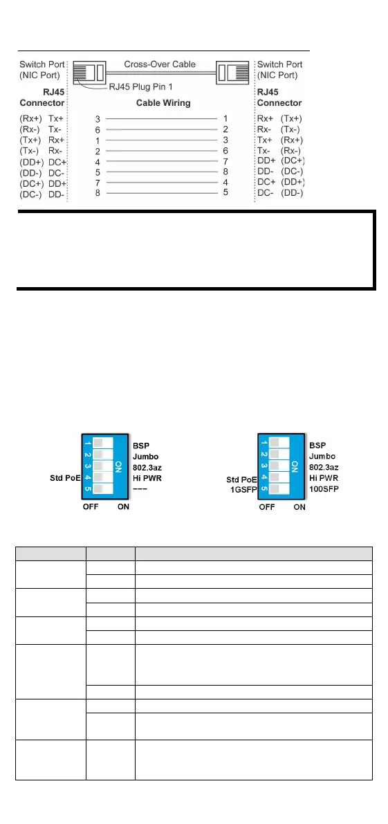
RJ45 (8-pin) to RJ45 (8-pin) Cross-Over Cable Wiring
If the PD only supports PoE MDI mode (V+, V+, V-, V- for pins 1,
2, 3, 6), choose a cross
-over Ethernet cable to connect the PD
and the EDS switch. If the PD only supports PoE MDI
-X mode (V-
-, V+, V+ for pins 1, 2, 3, 6), choose a straight-through
Ethernet cable between the PD and the EDS switch.
Redundant Power Inputs
Both power inputs can be connected simultaneously to live DC power
sources. If one power source fails, the other live source acts as a backup,
and automatically supplies all of the EDS’s power needs.
DIP Switch Settings
The default setting for each DIP Switch is OFF. The following table
explains the effect of setting the DIP Switches to the ON positions.
EDS-G205A-4PoE
EDS-G205A-4PoE-1GSFP
BSP
Enable broadcast storm protection
Disable broadcast storm protection
Jumbo Frame
Enable jumbo frame function
Disable jumbo frame function
802.3az
Enable the energy-efficient Ethernet function
Disable the energy-efficient Ethernet function
PoE High
Power
ON
Supports PoE high power output up to 36 W. PoE
high power is activated when an 802.3af or
802.3at connection is detected.
Supports standard PoE power output up to 30 W
(For SFP
OFF Supports 1000M SFP module
(For copper
– Serves no function (reserved for future use)

 Loading...