12
-422
-
422 wiring option,
first follow the 4
-wire RS-485 wiring
instructions given above.
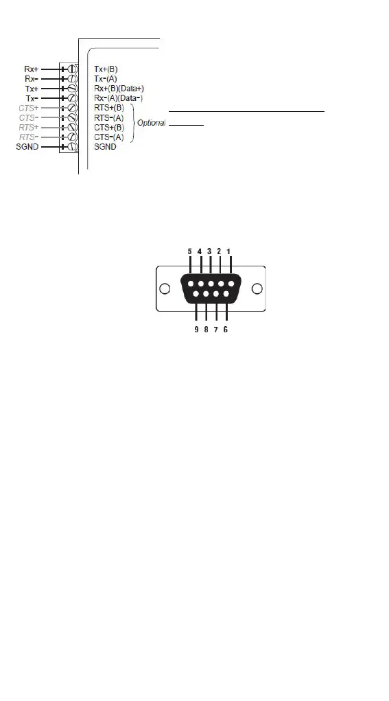
Optional RTS/CTS Handshaking
Signals
If your software is set up to send and
receive RTS/CTS signals over separate
wires, you should also connect from
RTS+(B) to CTS+, from RTS
-(A) to
-, from CTS+(B) to RTS+, and
STEP 4: Attach the RS-232 connector
Depending on your
application, use the
appropriate serial cable to
co
nnect from the TCC-100
s RS-232 female
-232
device, or to your
computer
’s COM port.
RS-232 Pin Assignment Diagram
STEP 5: Test the connection
After configuring the DIP switches, connecting the power, wiring the
terminal block, and attaching the RS-232 connector, we suggest using a
console terminal program, such as HyperTerminal or Moxa Terminal
Emulator, to test the connection. If you have an RS-422/485 serial board
(such as the Moxa CP-132, a 2-port RS-422/485 board) installed in your PC,
you can connect your PC’s COM port to the TCC-100’s RS-232 port, and then
connect the TCC-100’s RS-422/485 terminal block to one of the RS-422/485
serial board’s ports. Alternatively, if you have already set up an RS-422 or
RS-485 network, you can also connect the TCC-100’s RS-422/485 terminal
block directly to that network. Next, start HyperTerminal or Moxa Terminal
Emulator, and then open a connection to both the COM port, and the port
associated with the TCC-100’s RS-422/485 port. Test the connection by
typing a few characters on your PC’s keyboard. The characters you type
should show up in the HyperTerminal window that is currently inactive,
indicating that the typed characters were transmitted between the
TCC-100’s RS-232 port and RS-422/485 terminal block connector.
 Loading...