11
STEP 2: Attach the power supply
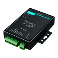
The TCC-100 is powered by an
external 12 to 48 VDC power supply.
To connect the power supply, run two
wires from the V+ and V
- terminals
the TCC’s 3-connector terminal
block to the DC power supply, as
shown in the figure. Once the power
supply is connected to its power
source, the PWR LED located on
the
’s top panel should turn red.
-100 series supports reverse power protection. That is
, it
will automatically detect which power wire is negative, and which
is positive.
STEP 3: Wire the terminal block
There are three wiring options available for connecting to the TCC-100’s
RS-422/485 terminal block.
-wire RS-485
2-wire RS-
485 wiring
option, connect three wires from
the
-100’s terminal block to the
opposite connection. As shown in the
figure, connect from Data+ to Data+,
from Data
- to Data-, and from SGND
4-wire RS-485
When using the 4
-wire RS-
485 wiring
option, connect five wires from
the
-100’s terminal block to the
opposite connection. As shown in the
figure, connect from Tx+(B) to Rx+,
from Tx
-(A) to Rx-, from Rx+(B) to
-(A) to Tx-, and from
ND.
 Loading...