20
ANALOG LEVEL INPUT (4-20mA Input) – CALIBRATION PROCEDURE
LEVEL INPUT ZERO - Parameter P.25
This parameter is used to make the display read zero feet of water with a Wet Well Level input of 4.0mA.
Calibration Procedure:
1. Apply a 4.0mA signal to the Wet Well Level Analog Input.
(Alternate Procedure - Pull the pressure transducer or bubbler tube out of the water.)
2. Scroll to the place in the System Setup Sub-Menu where Parameter P.25 is displayed.
3. Press the Scroll / Change mode push-button. (The Wet Well Level will be displayed.)
4. Use the Up / Down push-buttons to make the display read zero feet. Note: It is slow to change at first.
5. Perform the procedure below to calibrate the “LEVEL INPUT SPAN” Parameter.
LEVEL INPUT SPAN - Parameter P.24
This parameter is used to establish the Wet Well Level (in feet) that corresponds to an analog input of 20mA.
Calibration Procedure:
1. Apply a 20mA signal to the Wet Well Level Analog Input.
(Alternate Procedure – Subject the pressure transducer or bubbler tube to a known depth of water.)
2. Scroll to the place in the System Setup Sub-Menu where Parameter P.24 is displayed.
3. Press the Scroll / Change mode push-button. (The Wet Well Level will be displayed.)
4. Use the Up / Down push-buttons to make the display read the level (in feet of water) that your 20mA signal repre-
sents. Note: It is slow to change at first.
(Alternate Procedure – Use the Up / Down push-buttons to make the display read the number of feet of water
that the pressure transducer or the end of the bubbler tube is submerged under.)
5. Repeat the procedure above for the “LEVEL INPUT ZERO” Parameter.
Notes:
1. Level Display Span is what is displayed with a 20mA Level Input.
2. Parameter P.36 is used to set the decimal point position.
3. To find the Level Input Span Setting for other transducers use the following equation:
Pressure (psi) x 2.309 = Level (feet of water)
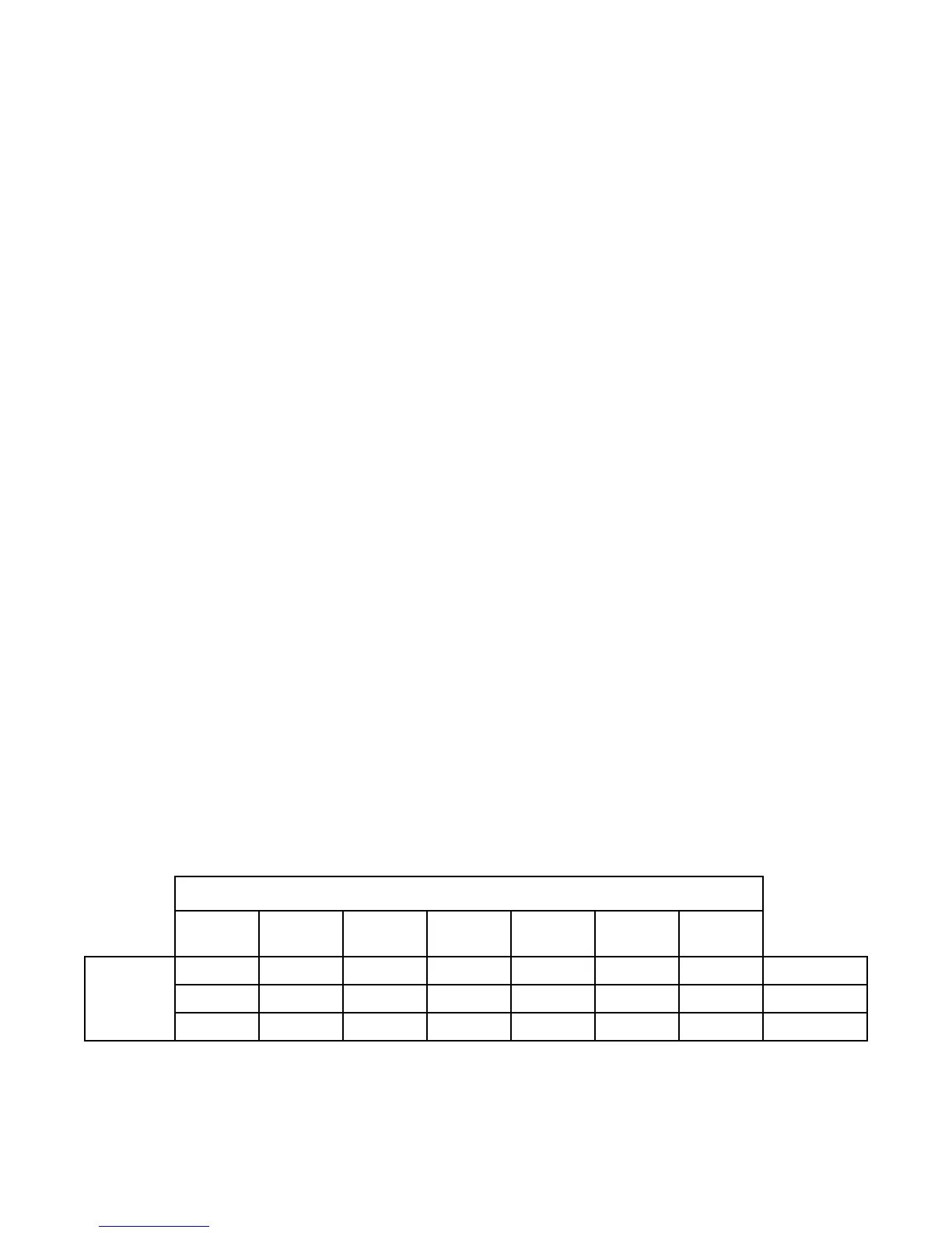
LEVEL DISPLAY SPAN VERSUS TRANSDUCER CALIBRATION
Transducer Calibration
4.33psi
@ 20mA
5.0psi
@ 20mA
10psi
@ 20mA
15psi
@ 20mA
60psi
@ 20mA
100psi
@ 20mA
- - - - 139 feet 231 feet
P.36 = 0
- 11.5 feet 23.1 feet 34.6 feet - -
P.36 = 1
9.99 feet - - - - -
P.36 = 2
Level
Display
Span
30psi
@ 20mA
-
69.3 feet
-
The following calibration is for the 4-20mA Analog Level Input (Parameter F.19 = 1) and does not apply when a 10 Electrode
Level Probe is used (Parameter F.19 = 2 or 3).
Parameters P.24 and P.25 show the Wet Well Level, while allowing the Up & Down push-buttons to be used to change the
internal numbers involved in calculating the displayed level. Therefore, the appropriate 4-20mA signal must be applied to the
Level Input during each step of the calibration procedure.
If Parameters P.24 and P.25 show 77.7 feet in the display, then Parameter F.19 is setup to follow the Level Probe input. To
calibrate the level display when using the Level Probe, the distance between the electrodes must be set on Parameter F.20,
and Parameters P.24 and P.25 are not used.
The 4-20mA Analog Level Input signal conditioning may be slowed down or speeded up using Parameter P.49.
 Loading...