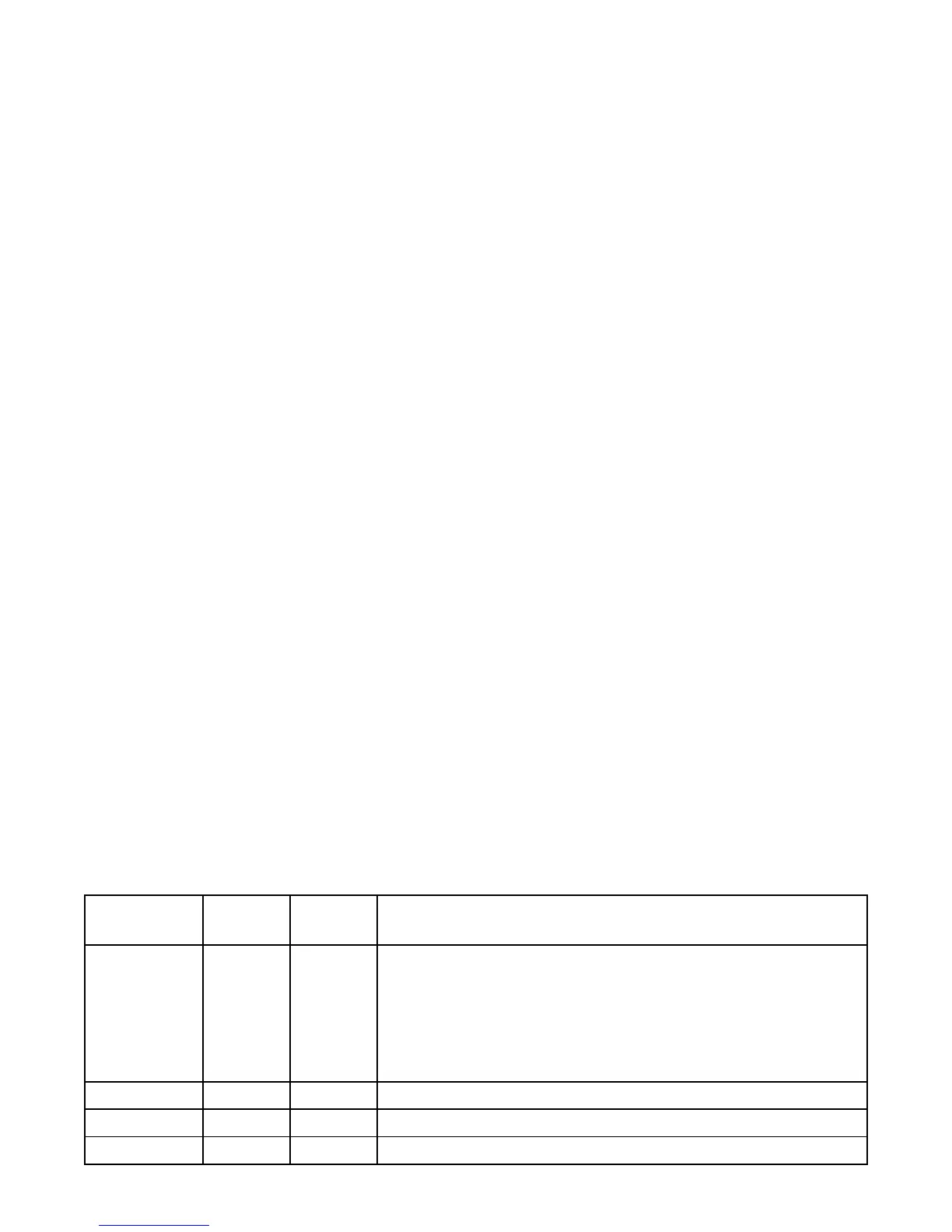
Parameter
Default
Value
Current
Value Setting Definitions
P.40
0
Flush Cycle Mode
0 = Flush Cycle Disabled
1 = Activated by Internal Time Delay as set on Parameter P.41
2 = Activated by External Time Clock by the Closure of a Discrete
Input programmed to perform Function 39. Note: Time Clock
Contacts may stay closed indefinitely, but must re-open in or-
der to reset logic for next Flush Cycle.
P.41
24 hours Delay Between Flush Cycles Range: 1 - 255 hours
P.42
2.5 feet Flush Cycle Stop Level Range: 0.2 - 99.9 feet
P.43
9.0 feet Flush Cycle Start Level Range: 0.2 - 99.9 feet
22
FLUSH CYCLE
The Flush Cycle feature is provided to periodically maximize the lift station’s discharge flow rate, to flush the
sludge build up from the bottom of the wet well and from the discharge pipe.
Flush Cycle Steps:
1. The “LEVEL” indicator begins to flash to indicate that the Flush Cycle has started.
2. Normal pump operation is suspended. Any pumps currently running are turned off.
3. Waits for the level to rise to the “Flush Cycle Start Level” set on Parameter P.43.
4. Turns on all available pumps with the Lag Pump Delay between each additional pump call.
5. Pumps the level down to the “Flush Cycle Stop Level” set on Parameter P.42.
6. Turns off all pumps.
7. The “LEVEL” indicator returns to normal to indicate that the Flush Cycle has ended.
Automatically Starting Flush Cycle:
A. Internal Time Delay - Expiration of “Delay Between Flush Cycles” set on Parameter P.41.
B. External Time Clock - Closure of a Discrete Input that is programmed to perform Function 39.
C. Programming the SCADA system to momentarily set Coil 139 in SCADA Register 40009.
Manually Starting / Stopping Flush Cycle:
Start - Press and hold the LEVEL Push-Button until the “LEVEL” indicator begins to flash.
(Momentarily set Coil 139 in SCADA Register 40009.)
Stop - Press and hold the LEVEL Push-Button until the “LEVEL” indicator returns to normal.
(Momentarily set Coil 140 in SCADA Register 40009.)
(Ends Flush Cycle even if it was started by the Time Delay or External Time Clock.)
Notes:
1. The Flush Cycle Feature only works in the “Pump Down” mode, (P.19 = 1). If Parameter P.19 is
changed to “Pump Up” mode (P.19 = 2), then Parameter P.40 will be set to “0”.
2. Use of an External Time Clock to start the Flush Cycle may be preferred, because it would provide
control over when the Flush Cycle occurs.
3. Where VFDs are used the analog Speed Reference will be forced to 100%.
4. The number of pumps called to run by the Flush Cycle logic is always limited by the following:
A. Parameter P.14 - Number of Pumps Allowed to Run At the Same Time.
B. Closed Discrete Inputs that are Programmed for Pump 1 (2, 3, 4) Disable, or All Pump Disable.
5. All backup systems must be setup so that they do not activate within the Flush Cycle operating
range set on Parameters P.42 and P.43.
6. The Low Level Float Backup (Discrete Input programmed for Function 32) will turn off all pumps upon
low level. Therefore, the Flush Cycle Stop Level must be set higher than the Low Level Float.
7. The Flush Cycle Status (Active or Inactive) may be read from Coil 141 in SCADA Register 40009.
FLUSH CYCLE - Setup Parameters
 Loading...