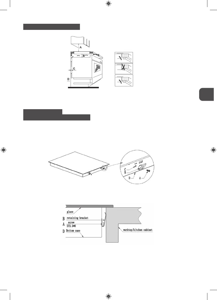
5.2. SPACE TO REAR OR SIDE WALL
A = 760 mm B = 50 mm (min) C = 30/20 mm (min)
D = Air Gap/Intake E = Air Exit (10/5 mm)
5.3. FIXING BRACKETS
BEFORE LOCATING THE FIXING BRACKETS
The unit should be placed on a stable, smooth surface (use the packaging). Do not apply force
onto the controls protruding from the hob.
Fix the hob on the work surface by screw four brackets on the bottom of hob (see picture)
after installation.
Adjust the bracket position to suit for different table top thickness.
a) Screw
b) Bracket
c) Screw Hole
d) Base of hotplate
49
MPM-45-IM-07, MPM-60-IM-04, MPM-60-IM-05_instrukcja_v03.indd 49MPM-45-IM-07, MPM-60-IM-04, MPM-60-IM-05_instrukcja_v03.indd 49 30.03.2020 10:1930.03.2020 10:19